How to Drive a Low-Side MOSFET with Arduino/ESP32
By far, the easiest way to switch a load on and off is to drive a MOSFET directly. This can be from a microcontroller or any other source that produces a logic high or low signal.
When driving a MOSFET directly from a 3.3V ESP32 or 5V Arduino, you must use a Logic Level MOSFET like the 6035AL used in this guide. Standard MOSFETs often require 10V at the gate to fully turn on, which a microcontroller cannot provide.
Why Use a Low-Side Switch Configuration?
In electronics, low-side switching is the most common way to control high-power loads like motors, LEDs, or heaters using a microcontroller. In this setup, the MOSFET is placed between the load and the ground (GND).
- Ease of Driving: Because the Source pin is connected directly to Ground, the Gate-to-Source voltage (VGS) is simple to calculate. For a logic-level MOSFET, you can often drive it directly from an Arduino or ESP32 pin without complex level-shifting.
- N-Channel Efficiency: N-Channel MOSFETs (the stars of low-side switching) generally have a much lower resistance (RDS(on)) and are more cost-effective than P-Channel MOSFETs.
- Safety & Stability: By using a pull-down resistor on the gate, you ensure the MOSFET stays OFF if the microcontroller signal is floating or during a reset, protecting your load from unexpected behavior.
While this configuration is highly efficient, remember that the load is always "hot" (connected to VCC). The switching happens on the return path to ground, which is the standard approach for most DC power control applications.
MOSFET Low-Side Switch Schematic
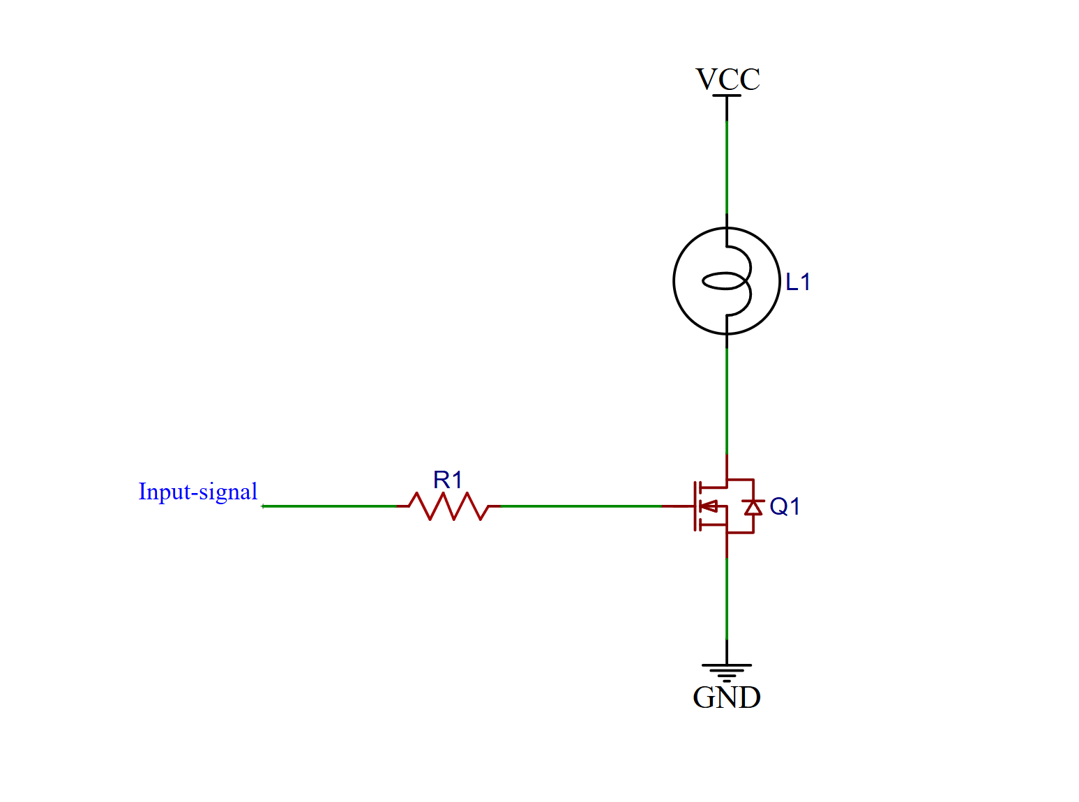
This circuit is just that. There are only a few components needed to make it work.
- The input signal, this can be of any voltage as long as it is digital, and it must match the MOSFET's specifications, more on that later.
- R1: A resistor to limit the current going to the gate of the MOSFET, to prevent ringing, and makes sure we don't overload the logic input signal.
- VCC: A second voltage high enough to drive the load.
- L1: The actual load, which, for this article, is a light bulb.
- Q1: The actual MOSFET. If we apply a voltage to its gate that is higher than its source, it will start to conduct.
- GND: If the MOSFET conducts, we have a path from VCC through the load and MOSFET to ground, turning the load on.
The load
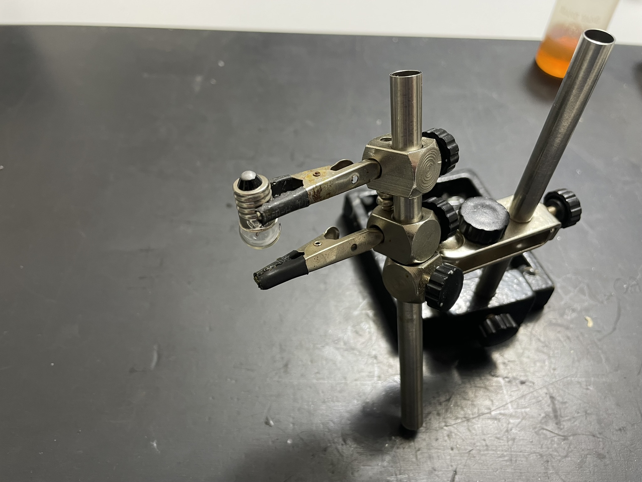
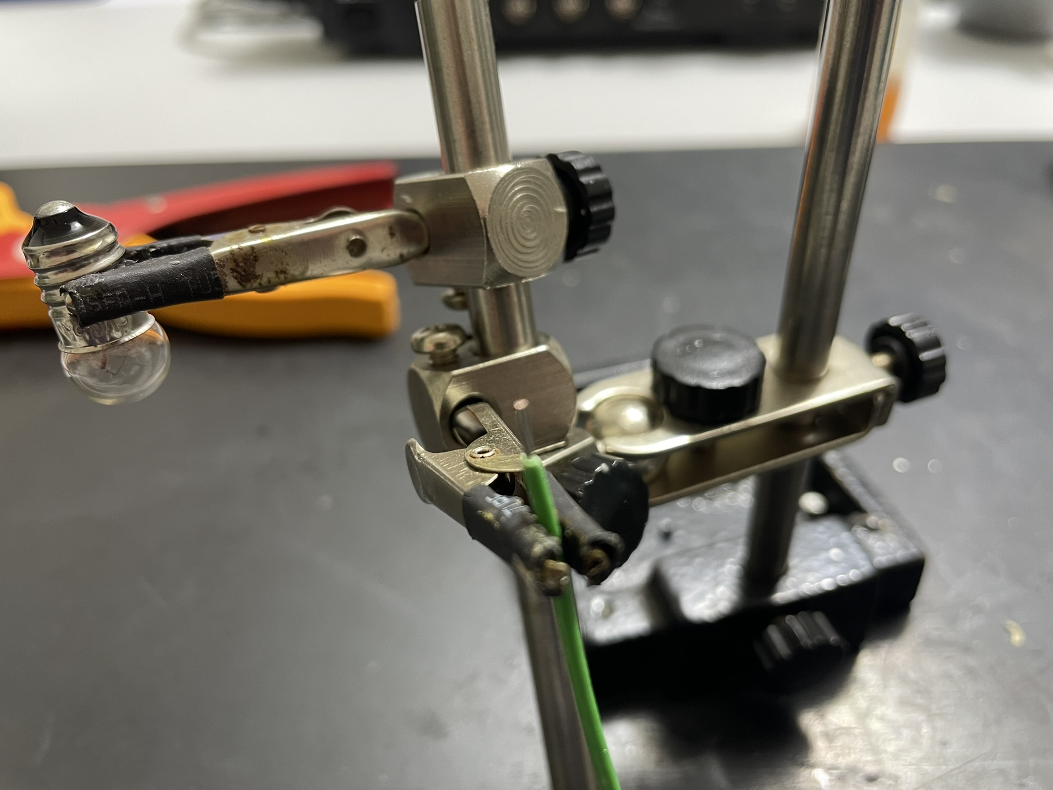
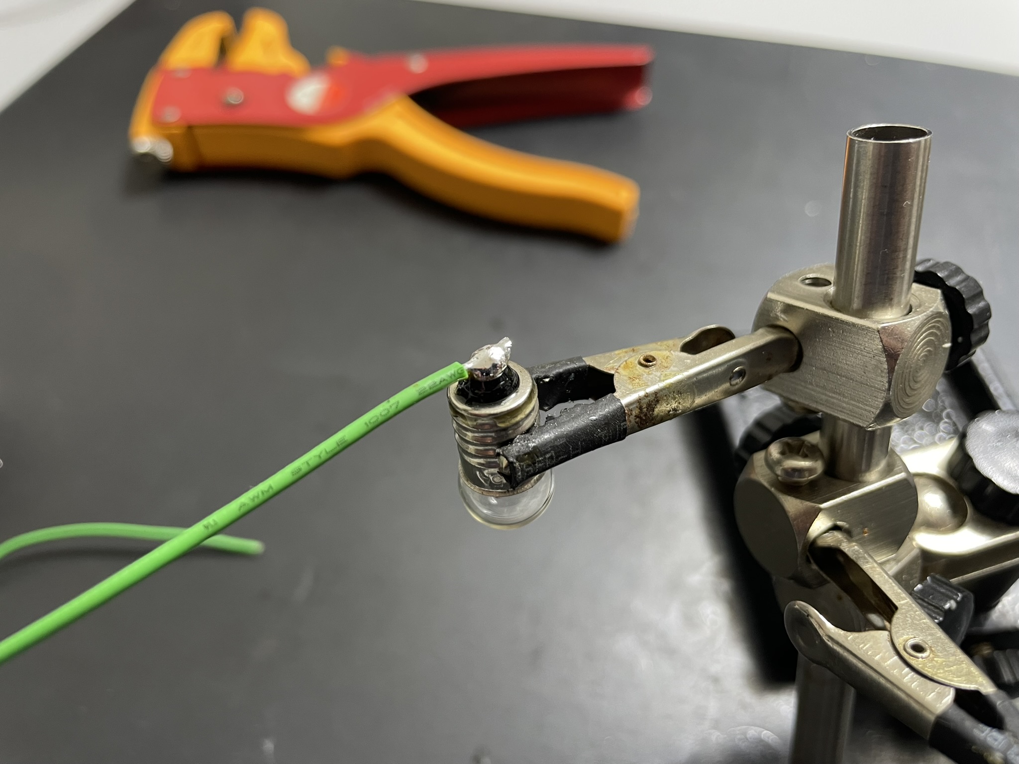
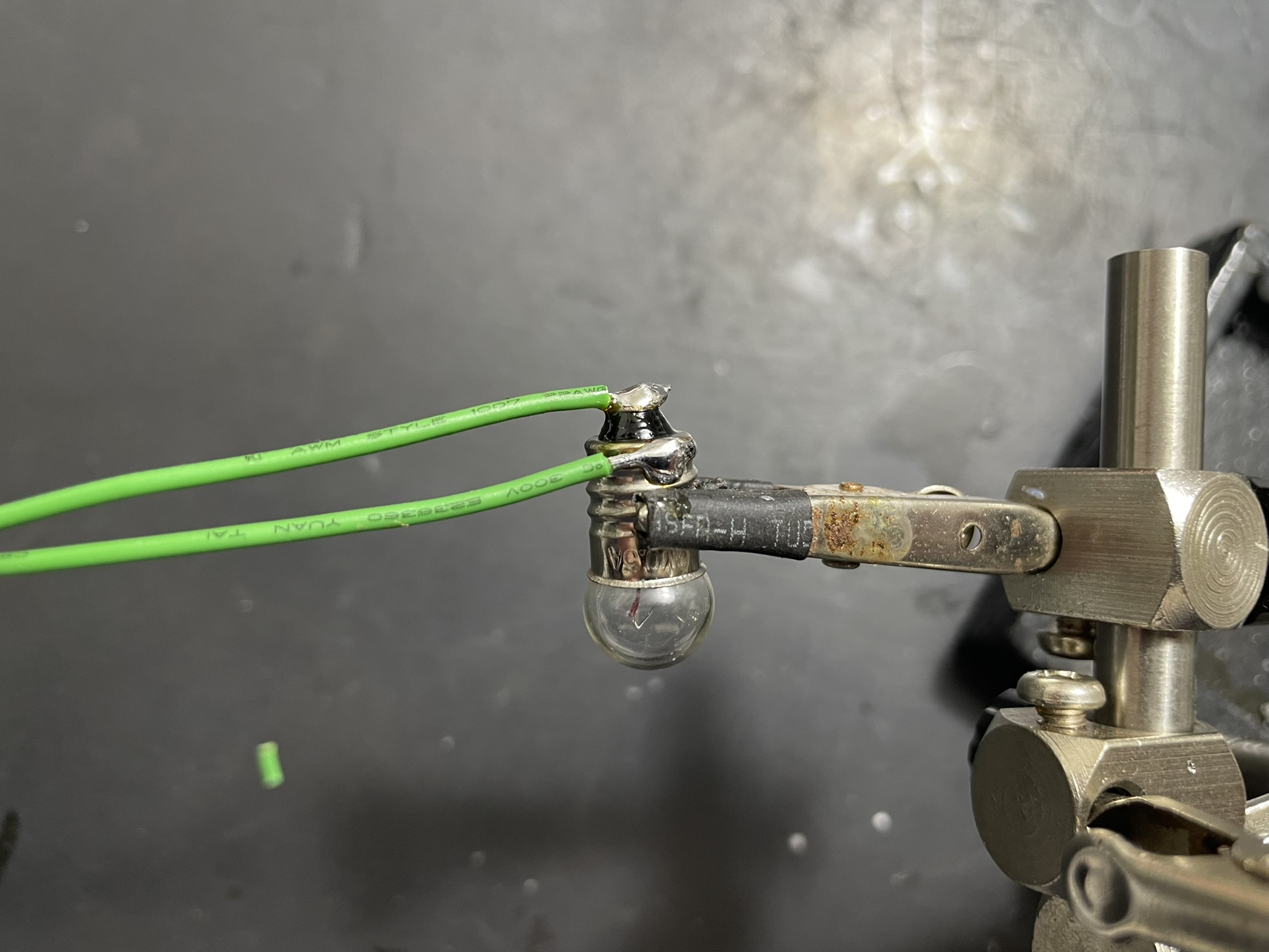
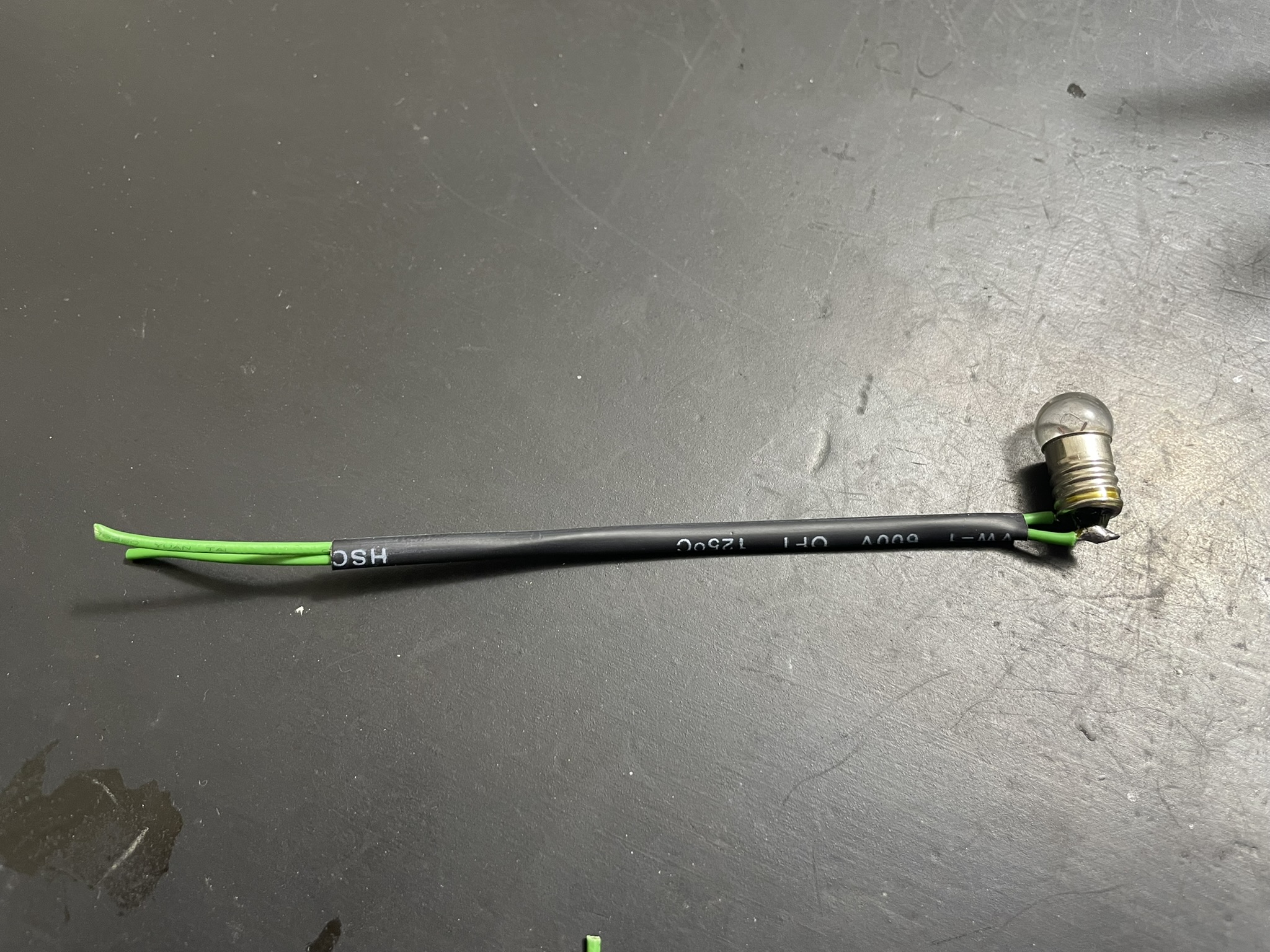
First, we need a load. I will use a very small bicycle light bulb, 6V at 0.3A, so 2 WATT at most, perfectly suitable for a breadboard experiment.
If I were to use a big light bulb, it would be very bright, and I would not be able to take good pictures or video of it.
It needs 2 wires, the order does not matter. With a bit of flux and quick soldering, we can actually solder the wires to the metal without destroying the bulb itself.
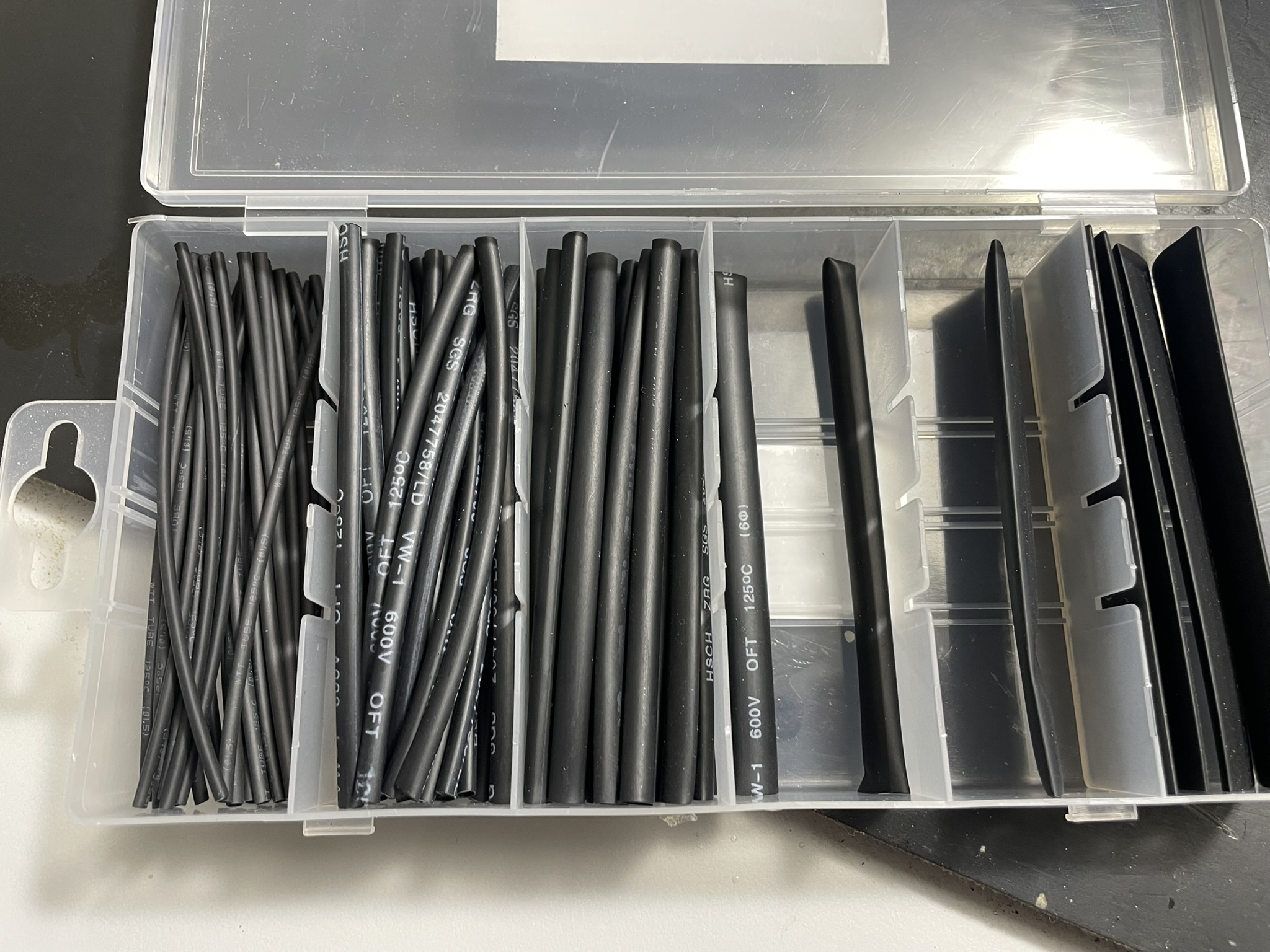
Then with a bit of heat shrink tube I made it a bit more appealing. In hindsight, the wires are a bit too long, might shorten them for the other articles in this series.
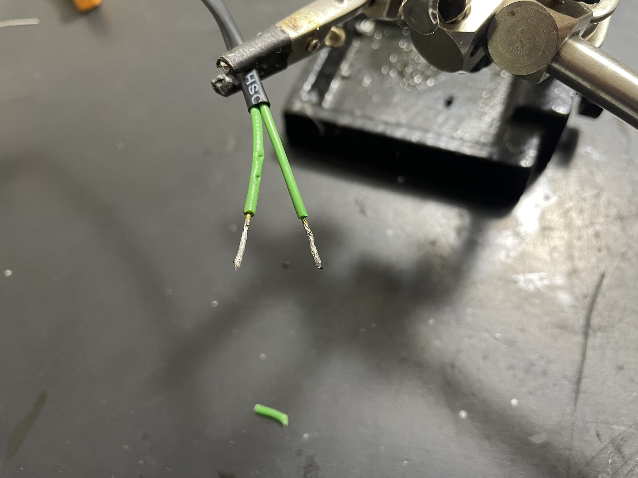
Finally, a bit of solder on the ends so I can put them in a breadboard.
Breadboard
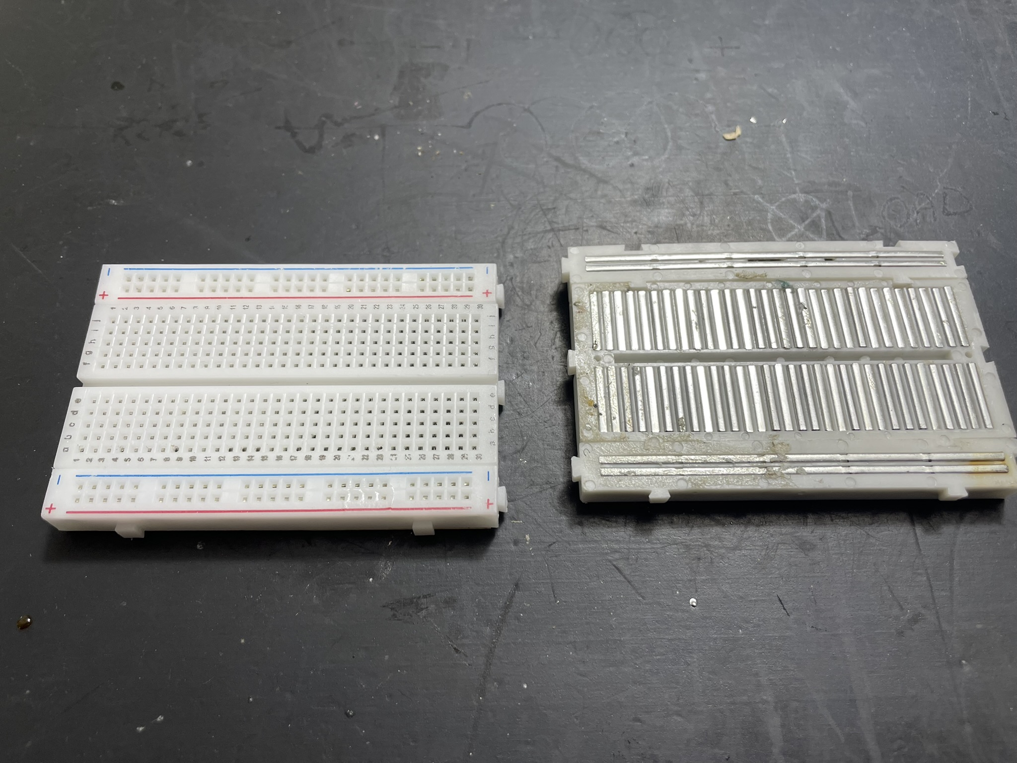
I will use a short breadboard for this, on the right side of the image you can see the underside of the board. Those metal strips are U shaped, so from the top you can insert the components legs and if they are in the same strip, they will connect.
Choosing an N-Channel MOSFET for Low-Side Switching
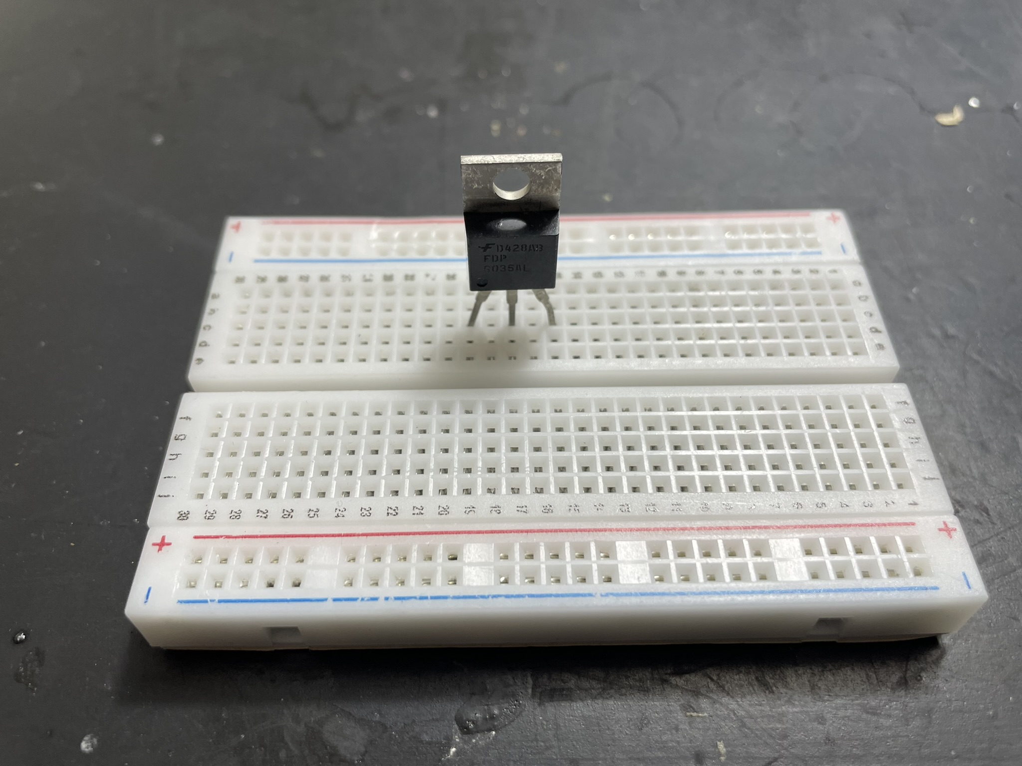
I inserted the MOSFET into the board, with the legs of it bent a bit outward, so we can better see what's connected to it.
Looking at the previous image, we can also see that each leg is in its own metal connection strip.
The MOSFET itself is the 6035AL logic level MOSFET. Even with 3.3V at its gate it can already switch 30A.
While the 6035AL can handle high current, remember that breadboards are limited. For loads over 5A, you should move from a breadboard to a PCB or soldered prototype to avoid melting the plastic.
From VCC to ground
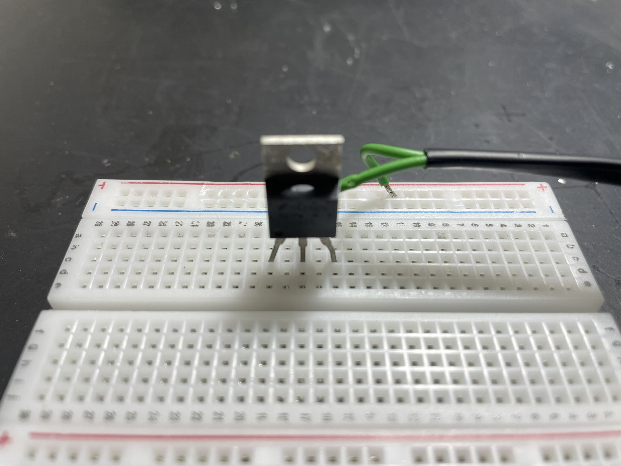
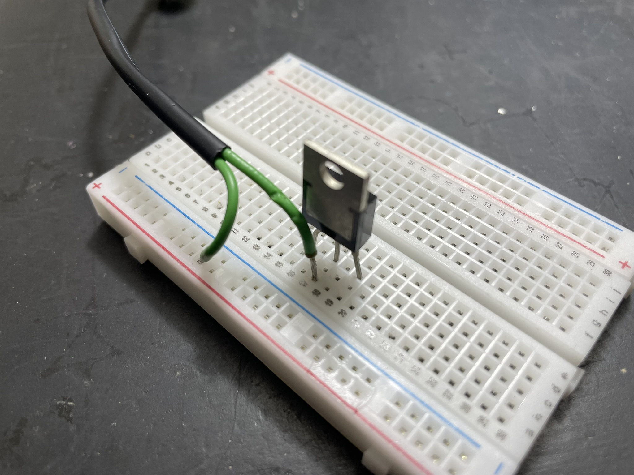
From left to right, the pins of the MOSFET are gate, drain and source.
- Gate controls the MOSFET
- Drain is where the switched power goes in.
- Source is where it comes out.
I want to power the bulb from the 2 rails at the top of the board.
So, to follow the circuit, the positive rail goes into the bulb, and the other end into the drain of the MOSFET.
If the MOSFET is on, that drain pin connects to the source pin.
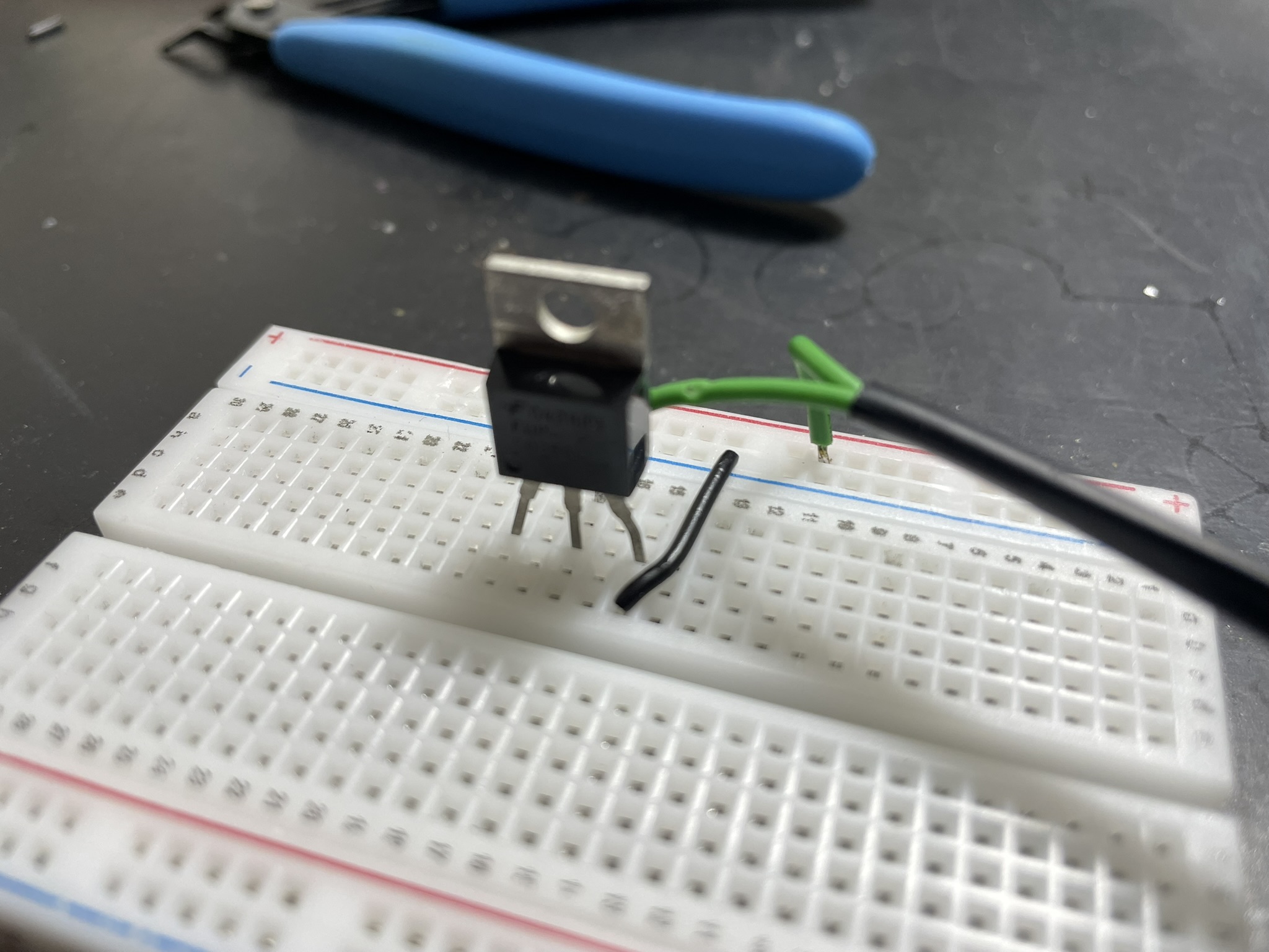
With that black wire, the source pin goes back to the negative rail of the board. Making the circuit complete (if the MOSFET is on of course).
Crucially, ensure your microcontroller ground is connected to the power supply ground. Without a common ground, the logic signal has no reference, and the MOSFET won't switch correctly.
Power supply
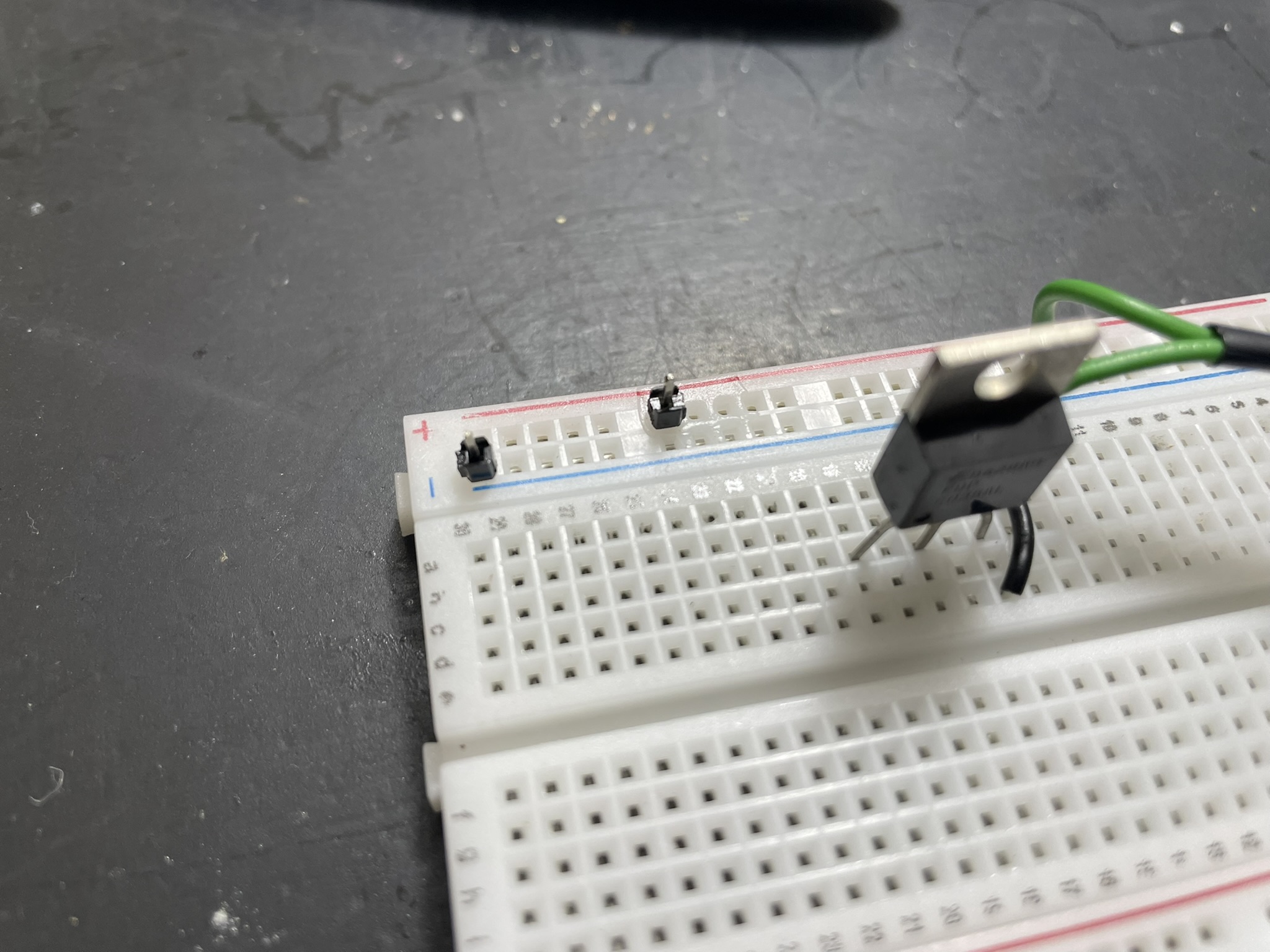
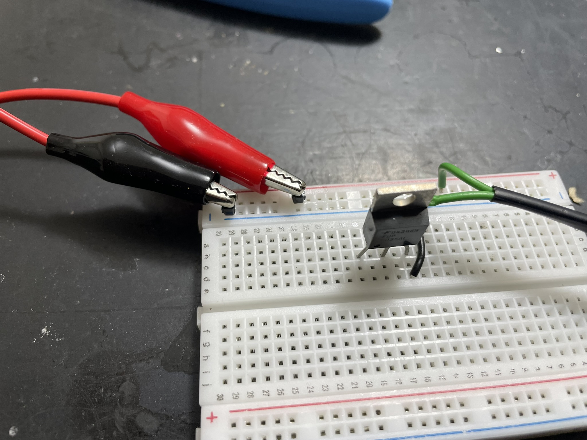
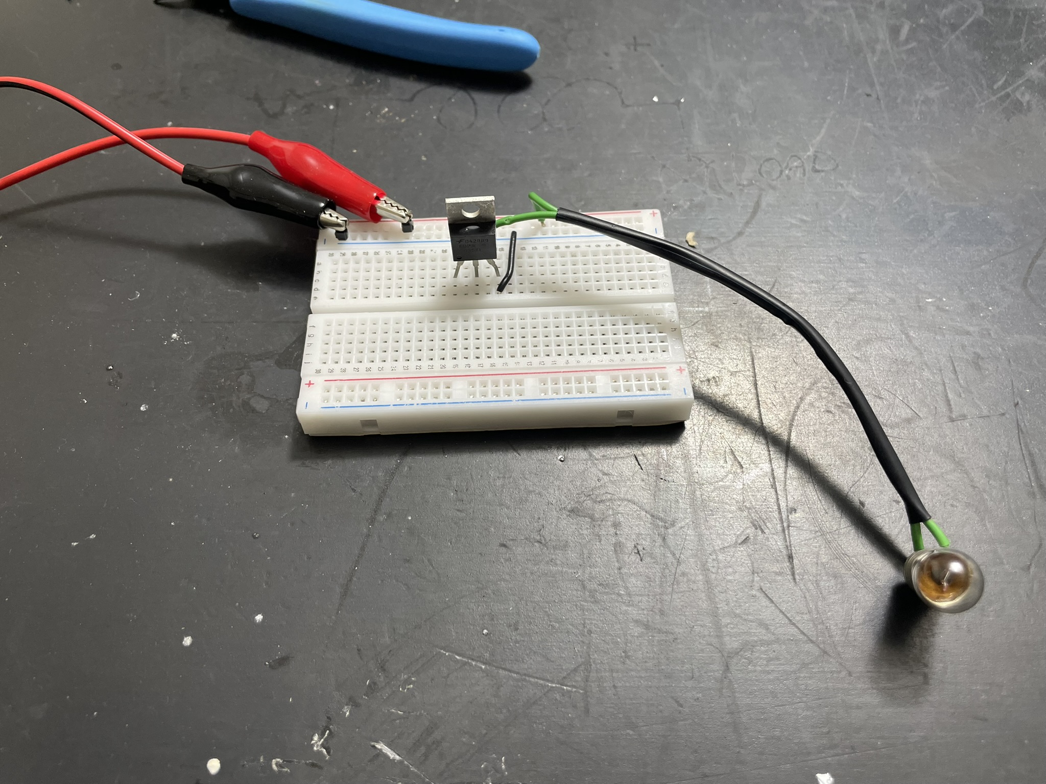
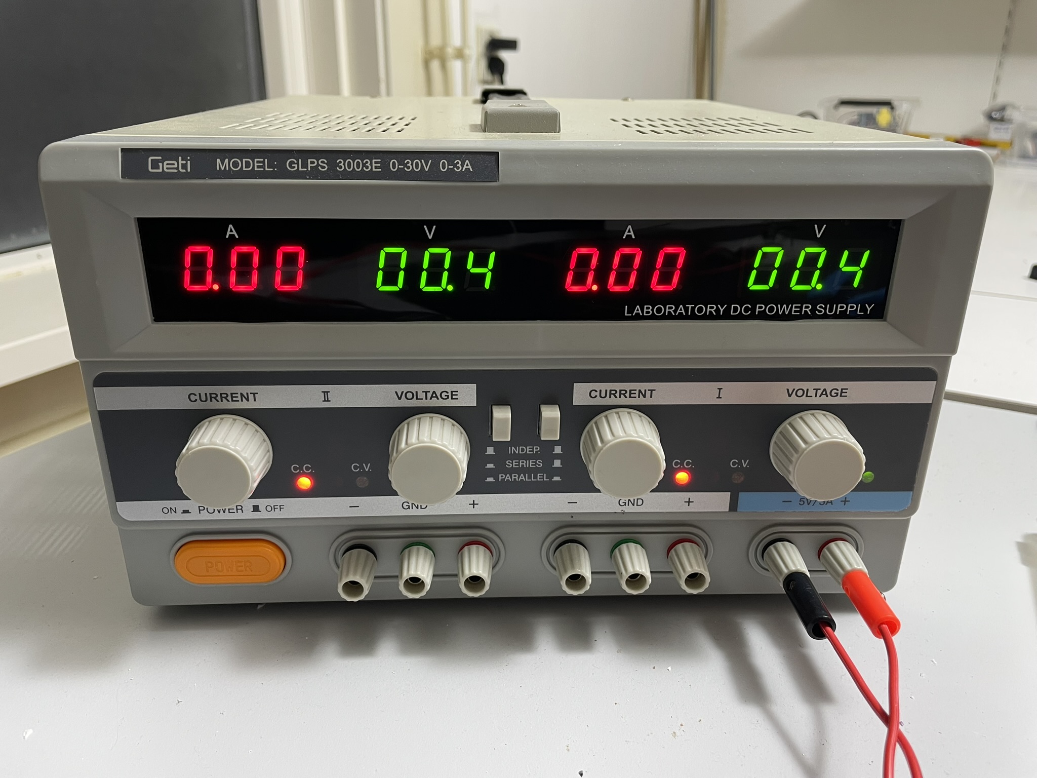
I use separate header pins to connect the board to an external power supply.
It shows zero volts, those are the variable supplies. But I have it plugged into the constant 5V supply at the most right connectors, those are always on and 5V is enough to get the bulb glowing.
Gate resistor
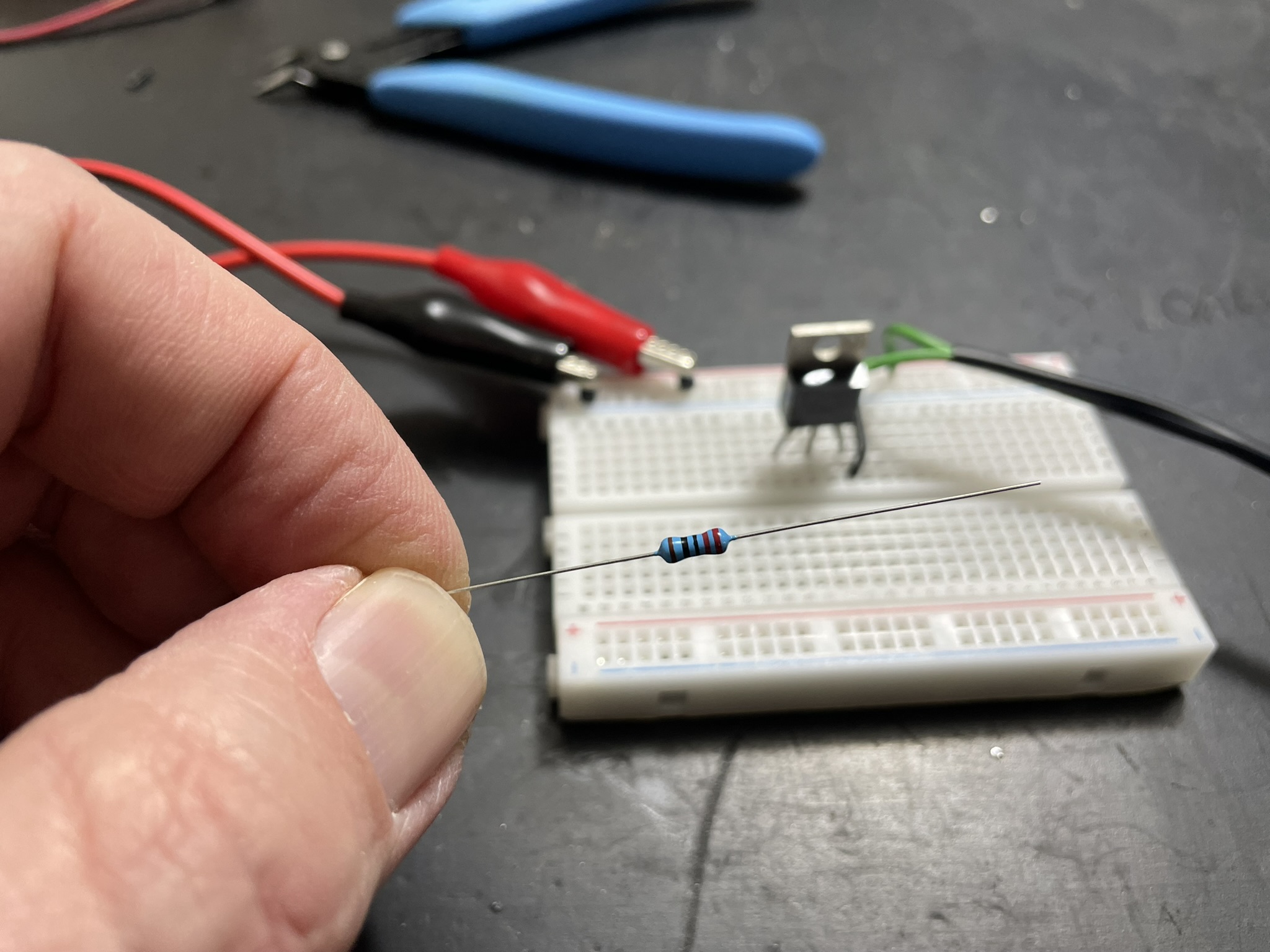
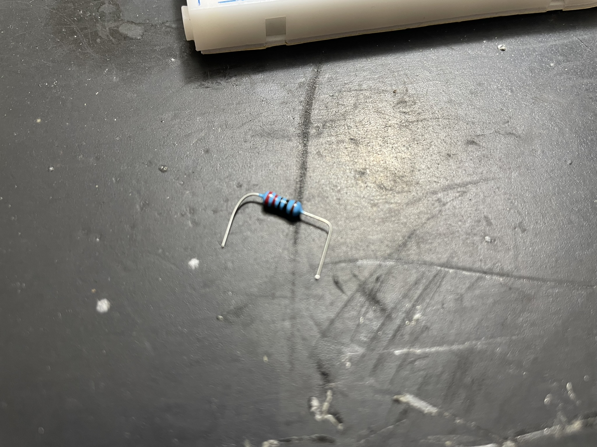
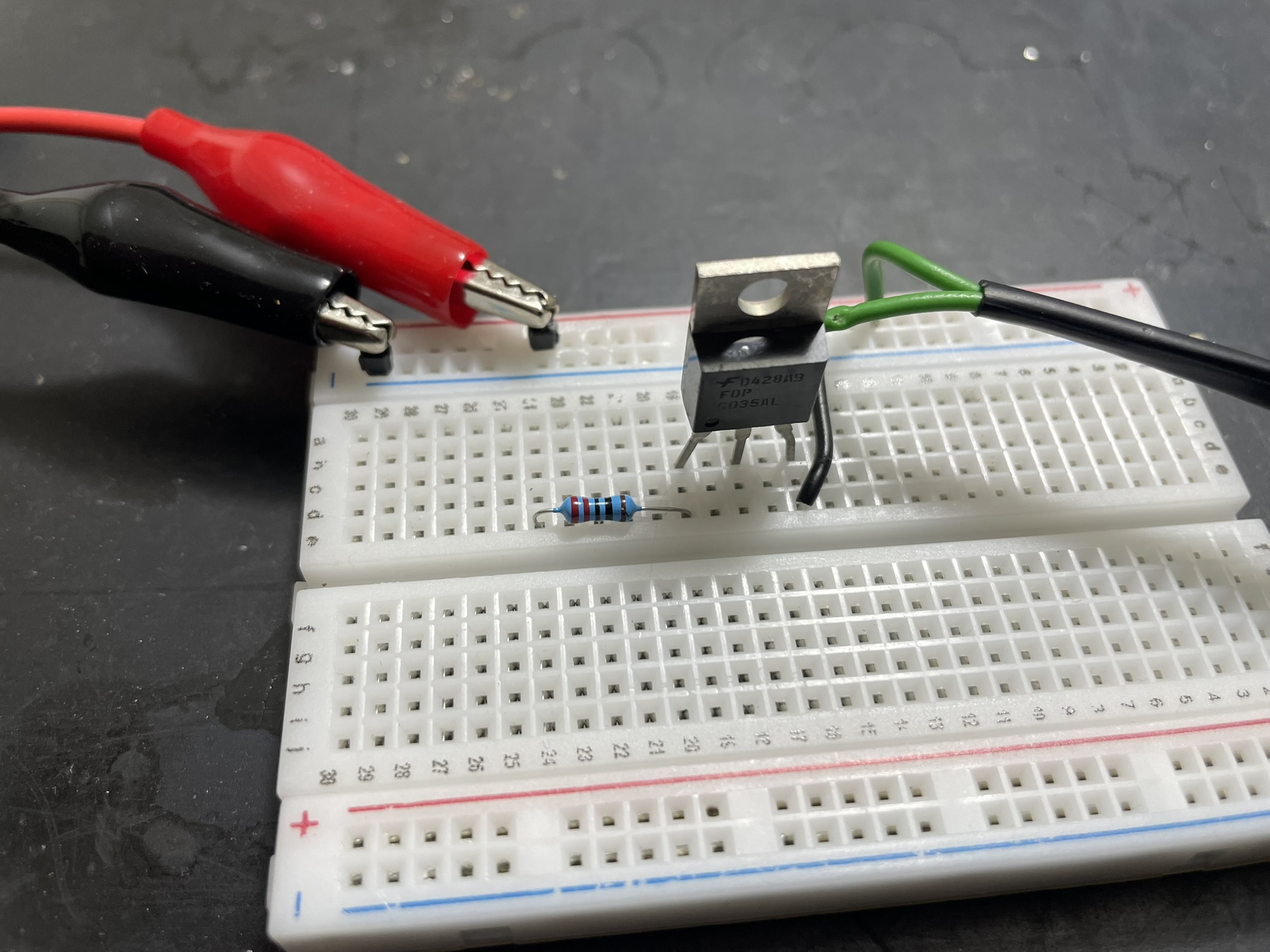
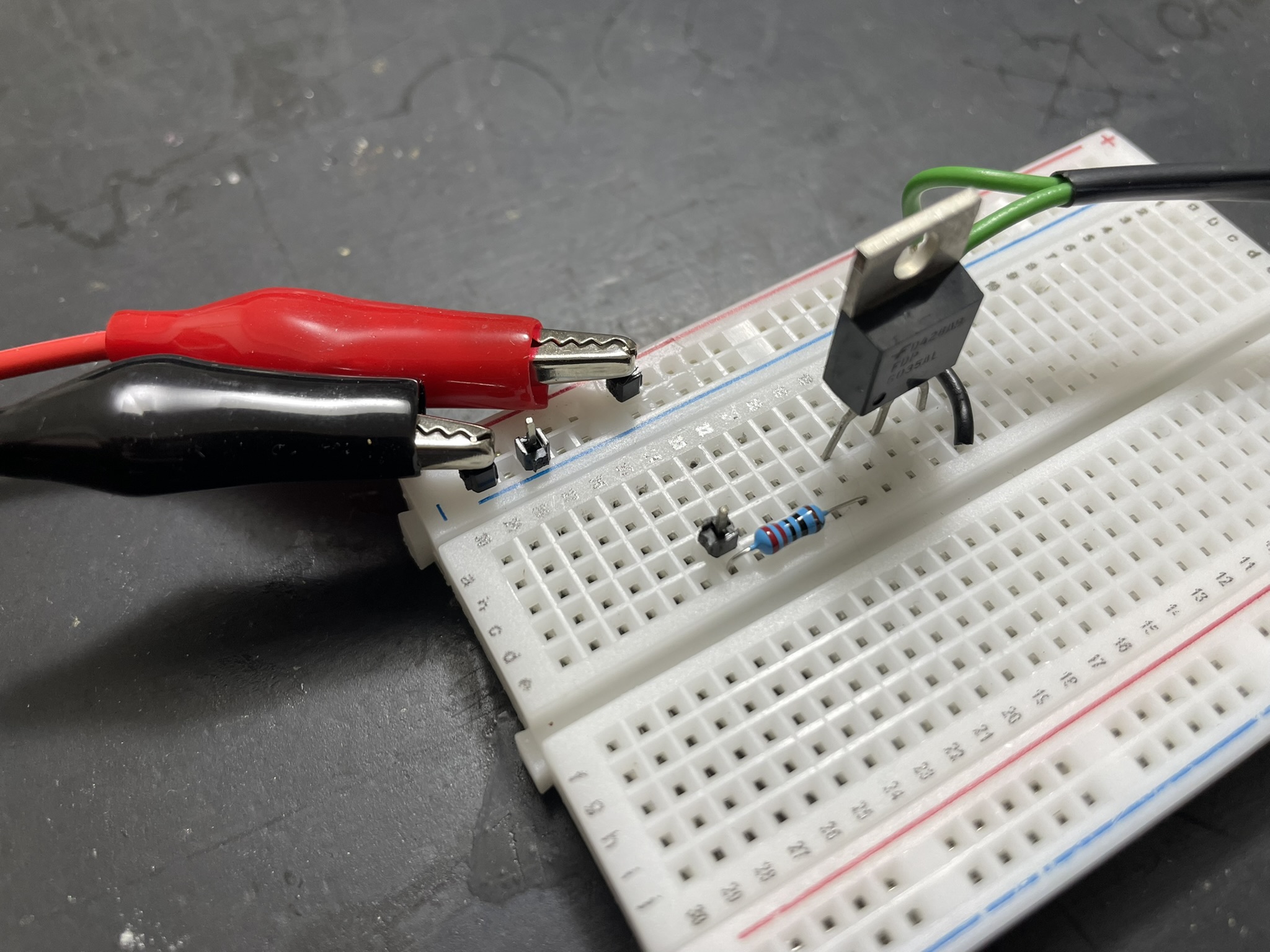
We need a resistor to protect the logic signal provider AND the gate of the MOSFET. Nothing special or high frequency is going on, so I just use a generic 220 Ohm resistor. That will keep both safe.
PWM input
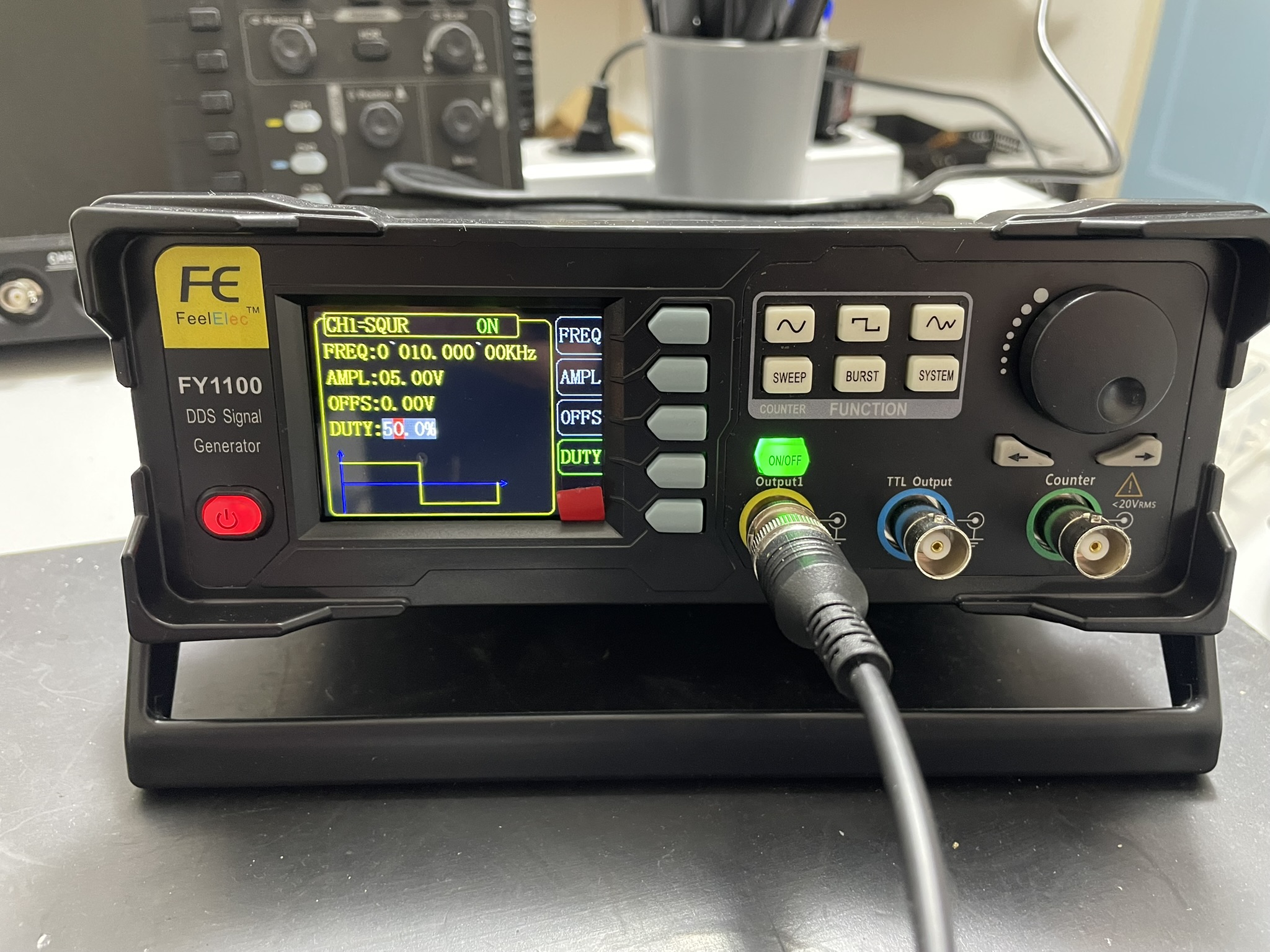
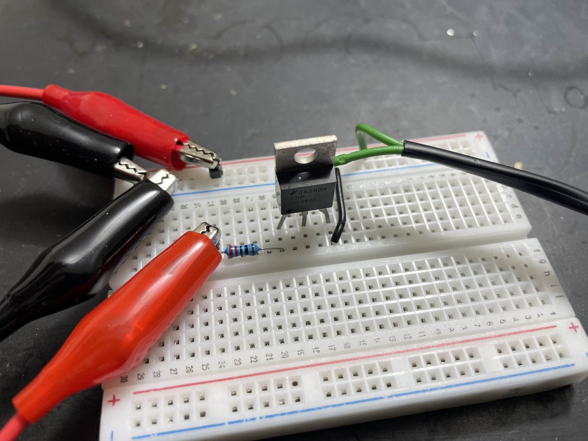
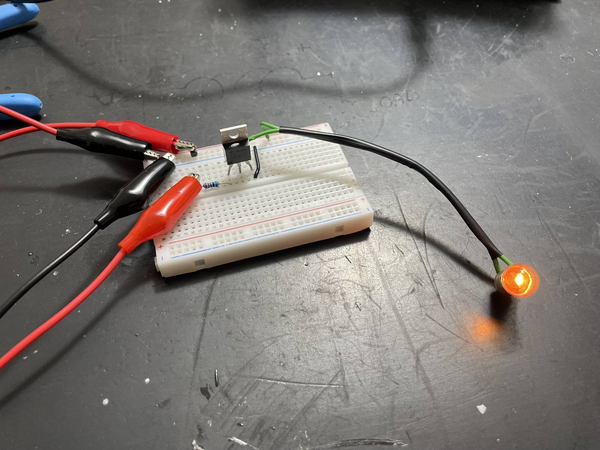
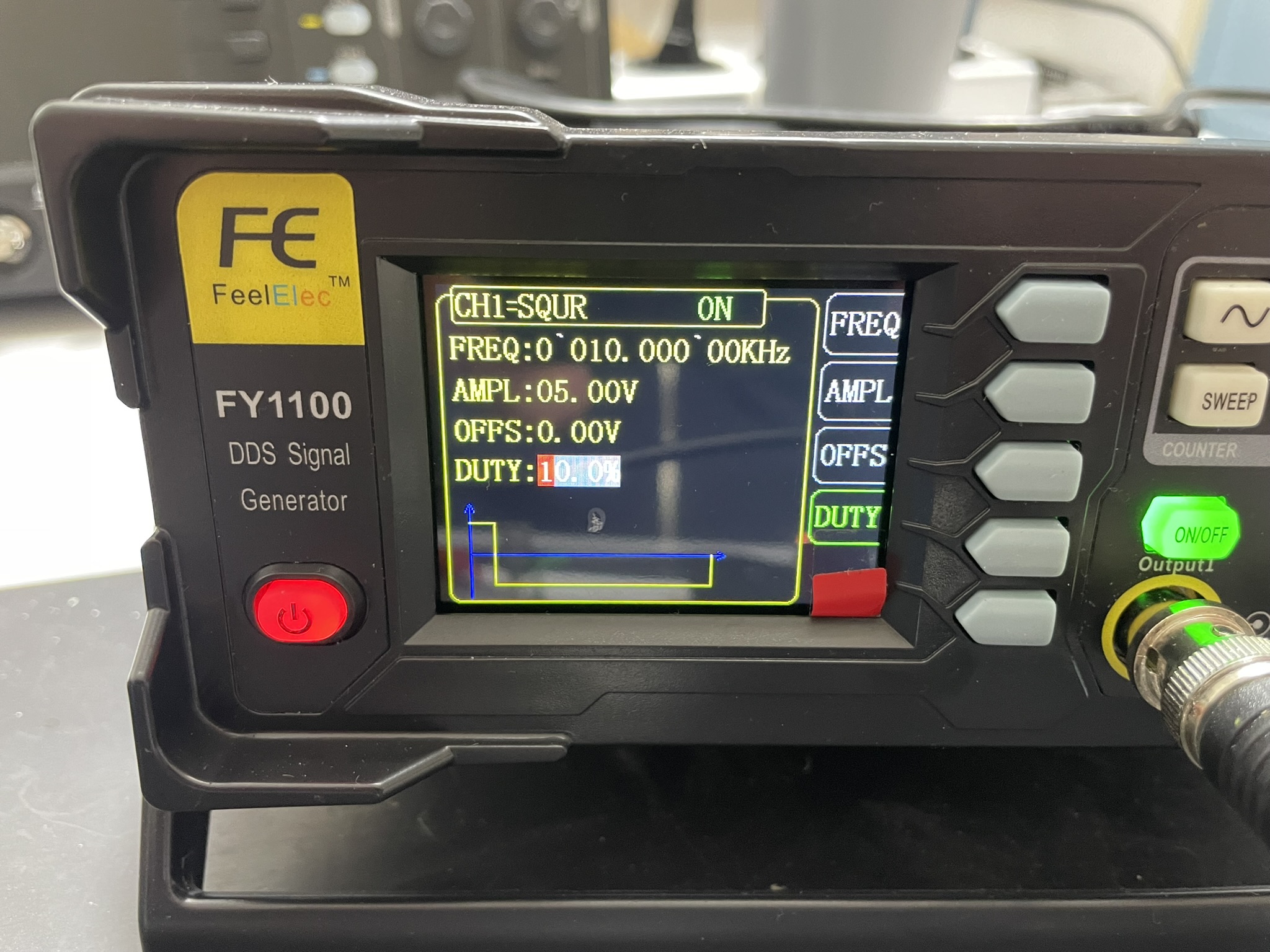
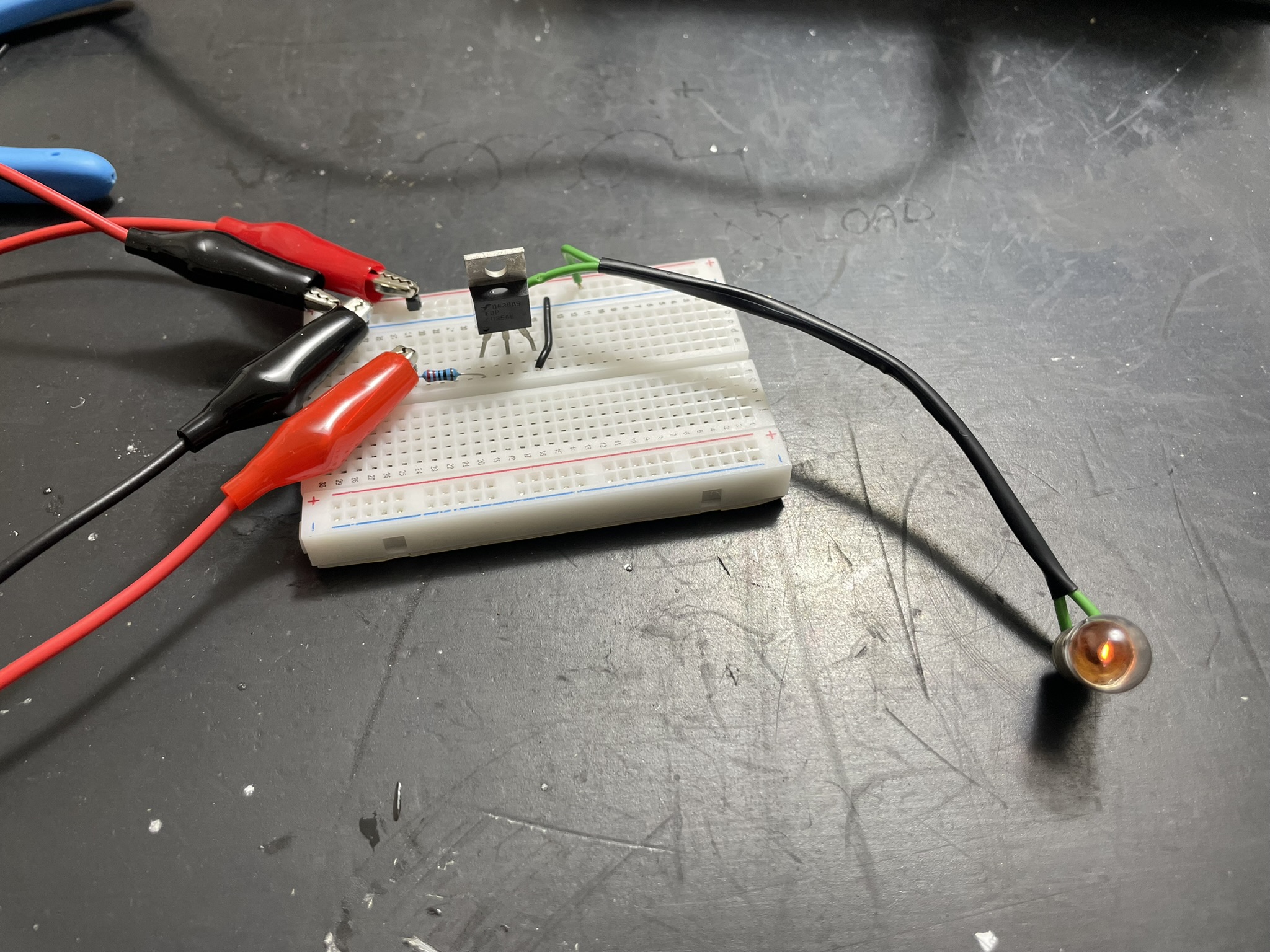
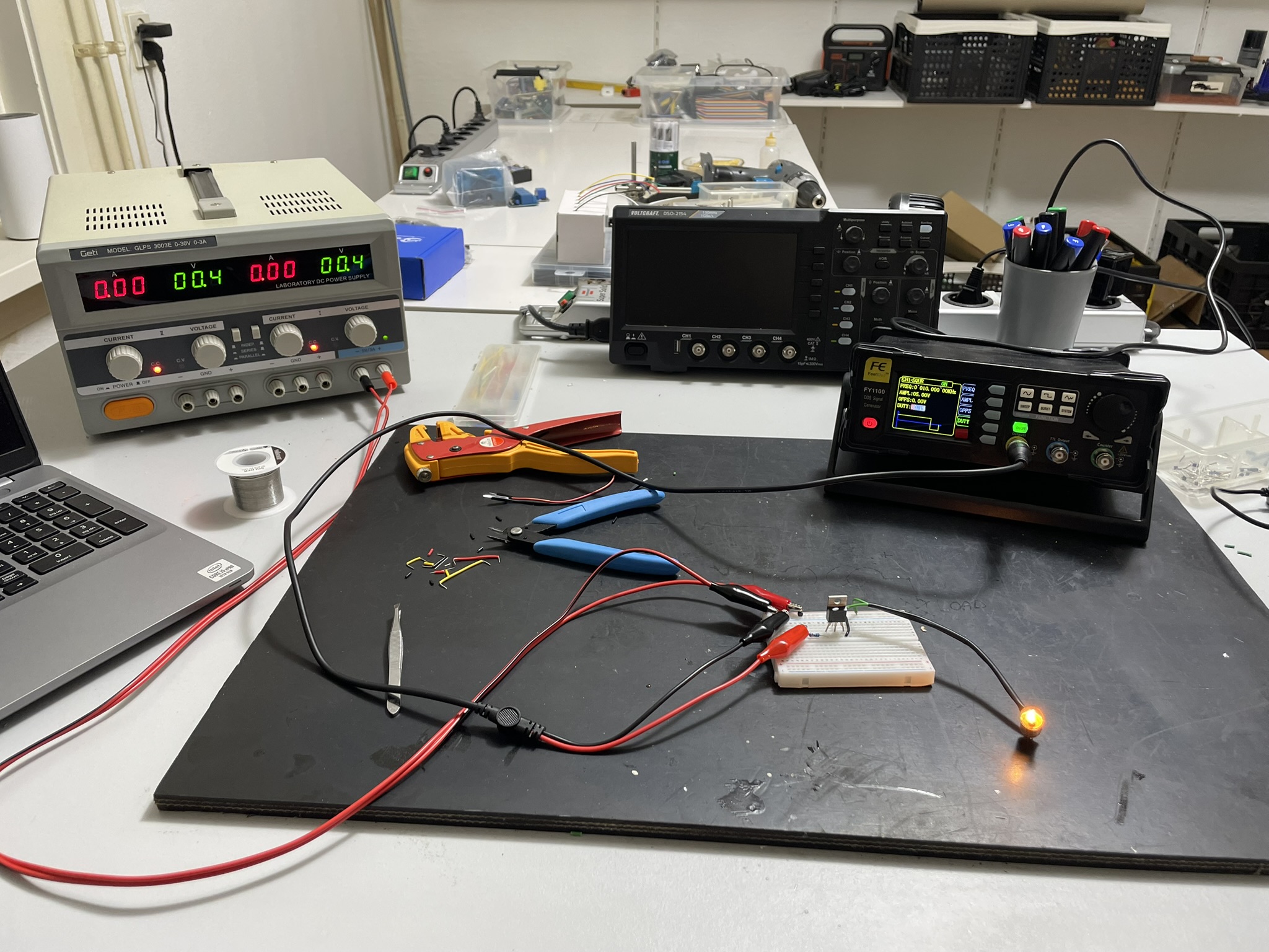
Now with the signal generator connected to the gate of the MOSFET and the source (which is also ground), we can now play with the duty cycle of the PWM signal.
And we can now see that the bulb indeed changes brightness when changing the duty-cycle.