Resistors Explained: From Ohm’s Law to Real-World Scoping
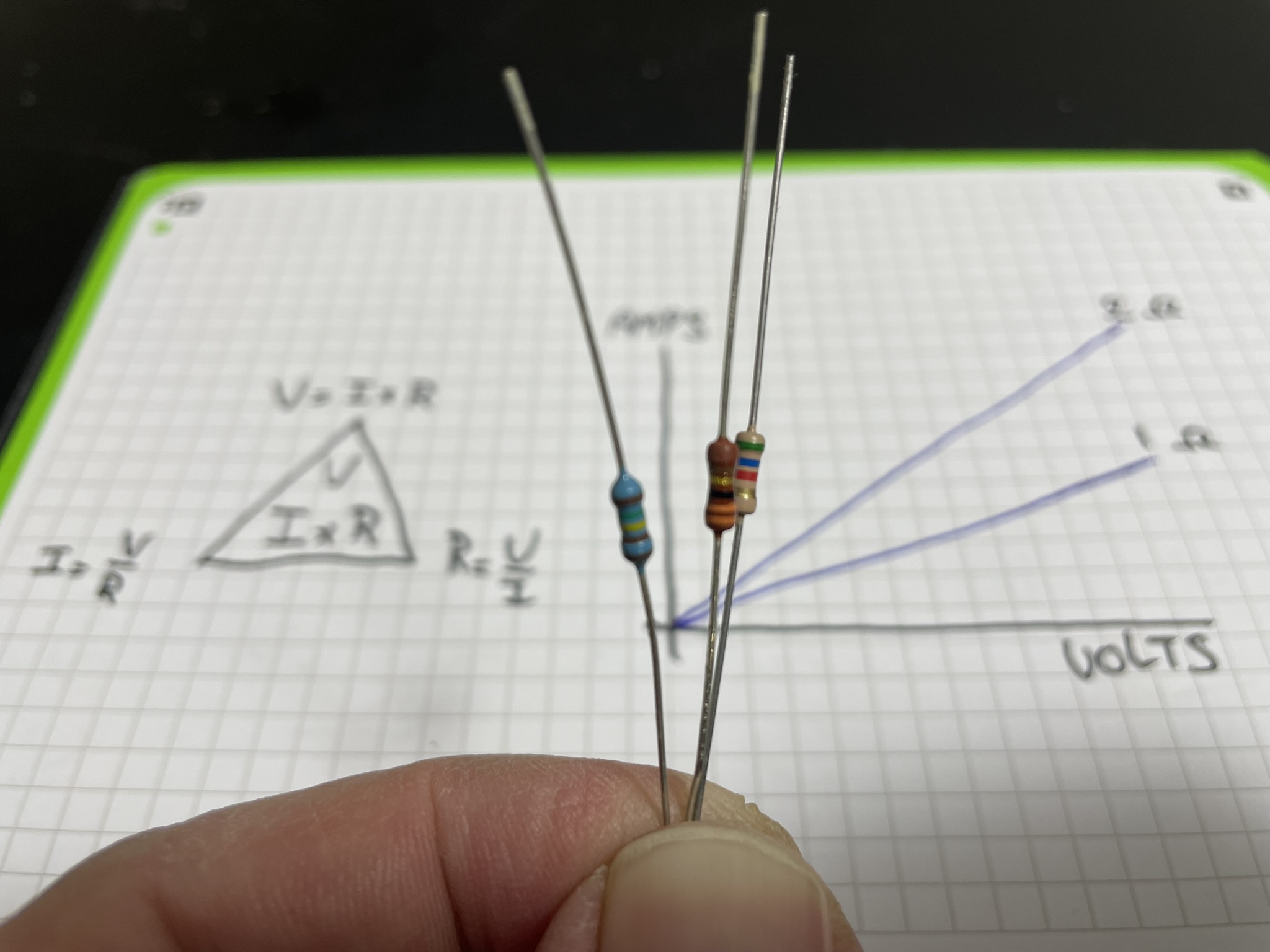
Whether you are just starting with an Arduino or designing complex analog circuits, the resistor is the most fundamental component you will encounter. It is the primary tool we use to control the flow of electricity.
In this article, we will start with the basic definitions. We will look at the math behind resistance, verify it with an oscilloscope to see its linearity in action, and walk through the most common real-world use cases on a breadboard.
Why do we actually use resistors?
If we look at any circuit board, the most numerous component we will see is the resistor. While they might seem like boring parts because they don't do something exciting like light up or spin a motor, they are crucial at maintaining circuit stability. Without them, most electronic projects would end in a puff of smoke.
We use resistors for three primary reasons:
- Preventing Short Circuits: A battery or power supply will output as much power as it is able to, unless we limit that. A resistor acts as a limiter, ensuring that current stays at a safe level so you don't melt your breadboard or blow a fuse.
- Protecting Components (Current Limiting): Components like LEDs and Transistors are delicate. They have a maximum current they can handle before their internal structure fails. A resistor limits the incoming current, keeping these parts within their safe operating limits.
- Steering and Dividing Voltage: By placing resistors in specific configurations (like a voltage divider), we can influence other voltages or scale them into another range. This is how we safely read a 12V battery level with a 3.3V microcontroller pin without destroying the input.
Essentially, if Voltage is the pressure and current is the flow, then the resistor is a restriction that allows only so much current at a certain pressure.
1. What is a resistor?
It's an electric sponge. Yes that sounds weird. And it is not about the absorption, it the porous structure inside it.
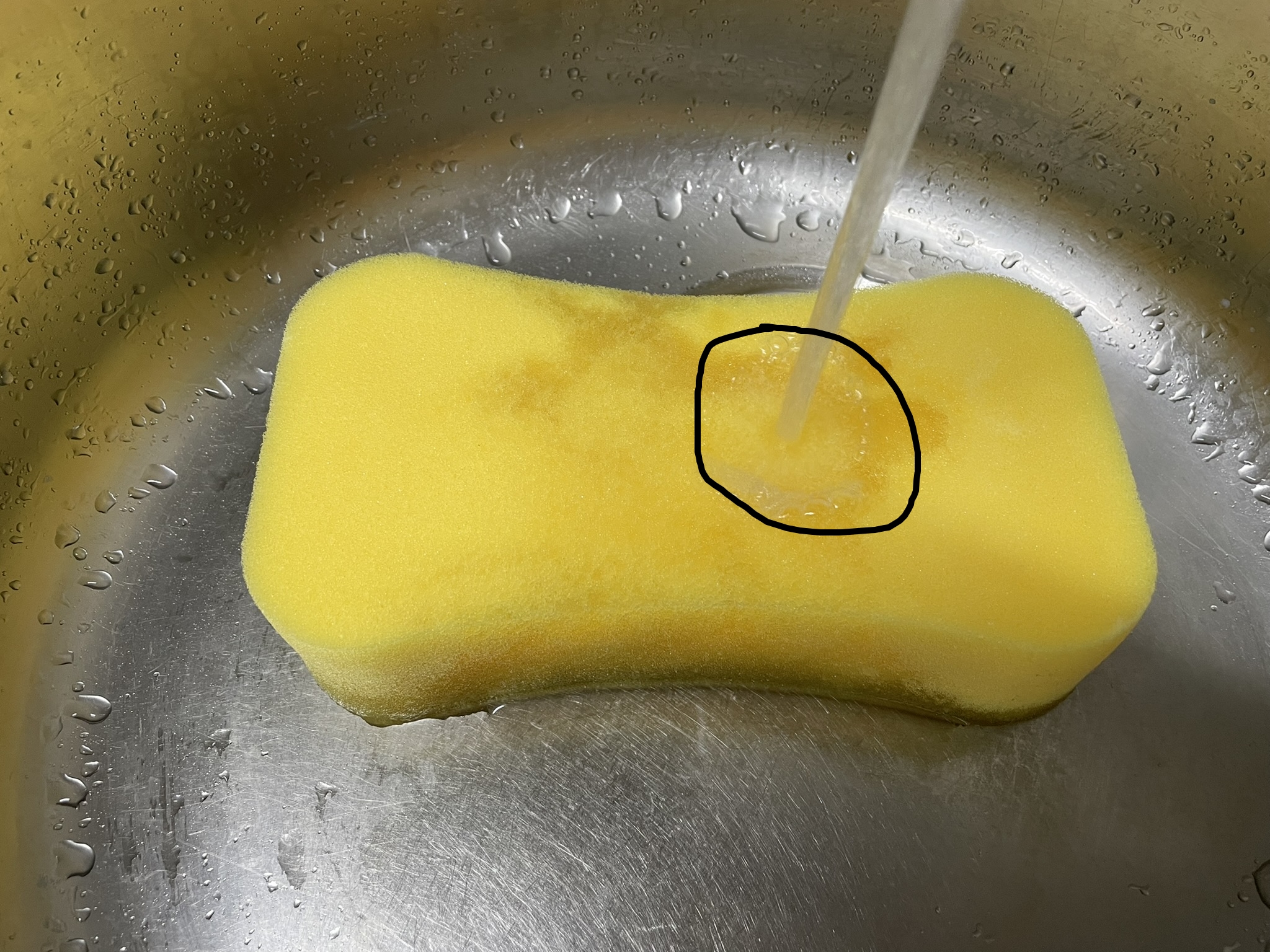
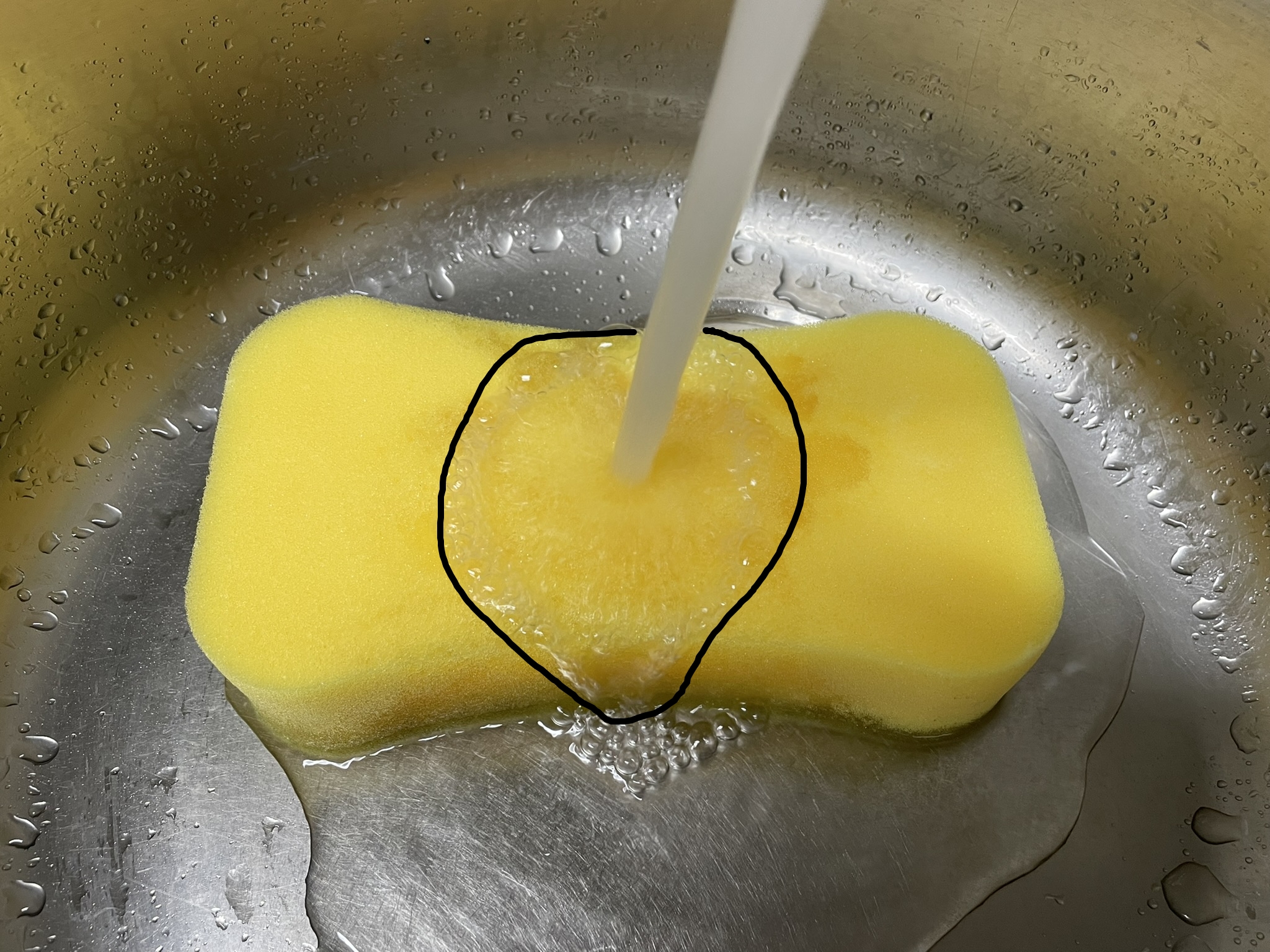
To demonstrate, I took a sponge and put a water stream on it.
The sponge can only transfer so much water from a certain area to the bottom. So all the water that can not be taken in spreads out, to where there is more sponge to take in the water.
And when I apply more pressure (voltage), it starts to spread out to more sponge area, to seek more transferring capacity.
The top area of the sponge in this case it the cross-section of a resistor. But with a flaw, it can overflow, and a resistor can not.
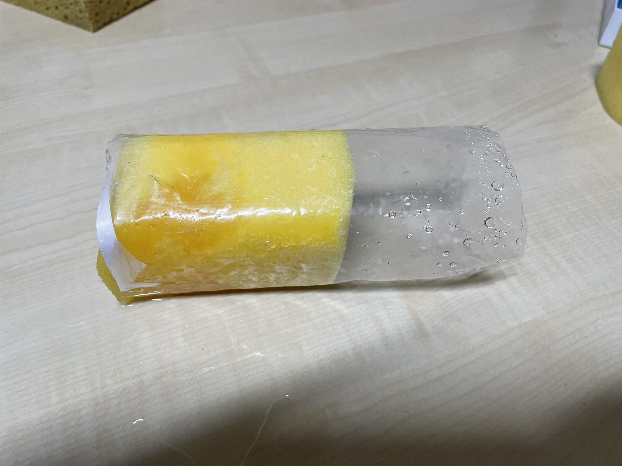
So I put the sponge in a tube, and now it is an actual resistor. The water now can no longer find other ways around to the bottom (ground).

In this first picture+video combo, I applied a low pressure (voltage). The sponge is able to take in the flow of water almost entirely.

But in this second picture+video pair, I applied more pressure (voltage). You can see the water level has risen, yet it is at stable level. The weight of the water has increased and applies more pressure to the sponges structure, forcing more water through. At this point the water flowing through is the same as the water added at the top.
This stability is linear in nature. The higher the water level, the more is let through by the sponge/resistor.
This applies to all conductive materials. More surface area means more capacity (less resistance), more length (height of sponge) means more resistance, and most important, each material has its own density, like copper (very low).
2. Ohm's law
There is a relation between the voltage over a resistor, the resistance itself and the current through the resistor.
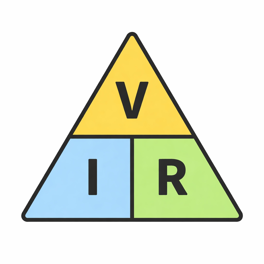
Alright, this image is a classic. It's a graphical representation of the formula V = I x R.
The letters mean the following:
- V = Voltage, the pressure of electricity trying to push current through the resistor.
- I = Current, the actual amount or flow of electricity through the resistor.
- R = Resistance
Putting this formula in a triangle makes it easier for us to morphe this law into 3 variations, depending on which of the properties we want to calculate.
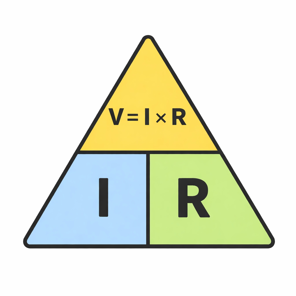
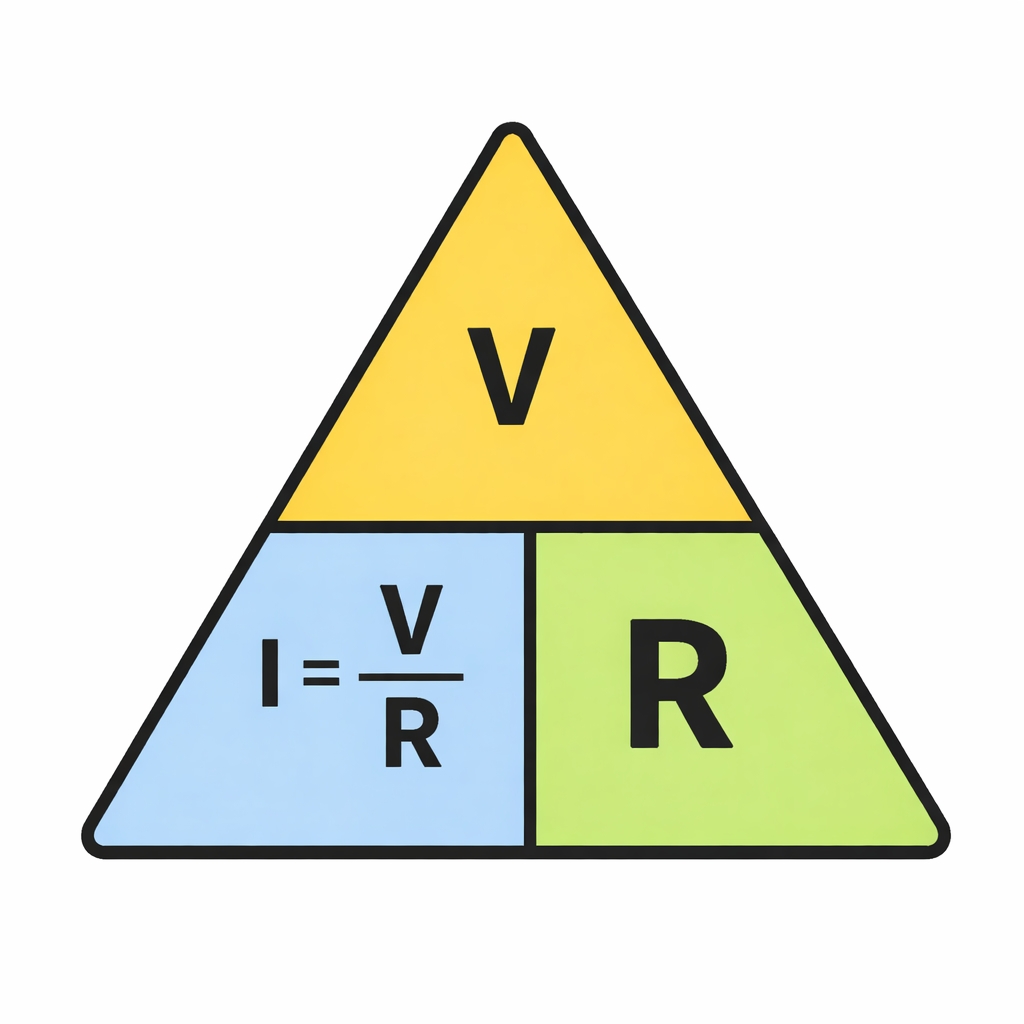
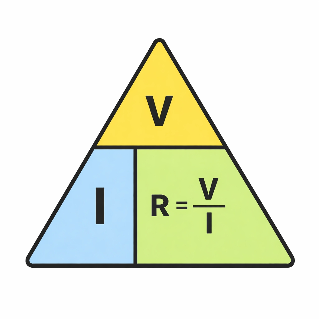
I hope that makes sense visually. I'll write them out for us bellow and then follow with a bit of explanation.
Ohm's Law Reference Table
| Goal | Formula | Translation |
|---|---|---|
| Calculate Voltage | V = I x R | Voltage = Current x Resistance |
| Calculate Current | I = V / R | Current = Voltage / Resistance |
| Calculate Resistance | R = V / I | Resistance = Voltage / Current |
Some explaining from the point of voltage.
V = I x R, Assume I = 1 and R = 1, that makes V also 1
If we increase the incoming flow of electricity, the current (I), The resistor will not automatically let more current through (remember the sponge videos). It will build up in front of the resistor in the form of presure/voltage (V).
That added pressure DOES force more current through the resistor, until the voltage and current are in balance again.
Same works for the resistance, If that increases, the voltage in front of the resistor will also rise, to equalize the system.
This also works the other way around, less current, means less voltage needed and the same for lower resistance, also less voltage needed.
I think this is a good place to note that:
- V (Voltage) is measured in Volts
- I (current) is measured in Amps
- R (Resistance) is measured in Ohms (Ω)
3. Visualizing Linearity on the Scope
- The I-V Curve: Why resistors are called "linear" components.
- The Setup: How to hook up a resistor to an oscilloscope in XY mode.
- The Result: Seeing the straight-line relationship between voltage and current.
SIDENOTE:
4. Practical Case Study: LED Current Limiting
- The Problem: Why an LED will burn out without a resistor.
- The Calculation: Using Ohm's Law to find the perfect resistor value (e.g., 220Ω for 5V).
- Breadboard Build: Step-by-step wiring and measurement.
5. Practical Case Study: Transistor Base Current
- The Role: Using a resistor to "trigger" a BJT transistor (like the BC547).
- Saturation: Why we need to limit current to protect the transistor's base.
- Breadboard Build: Switching a small load with a logic signal.
Resistors as signal protectors (Pull-ups & pull-downs)
- Floating Pins: What happens when a microcontroller pin isn't connected to anything.
- The Solution: How a 10kΩ resistor ensures a stable "High" or "Low" state.
How to read resistor color codes
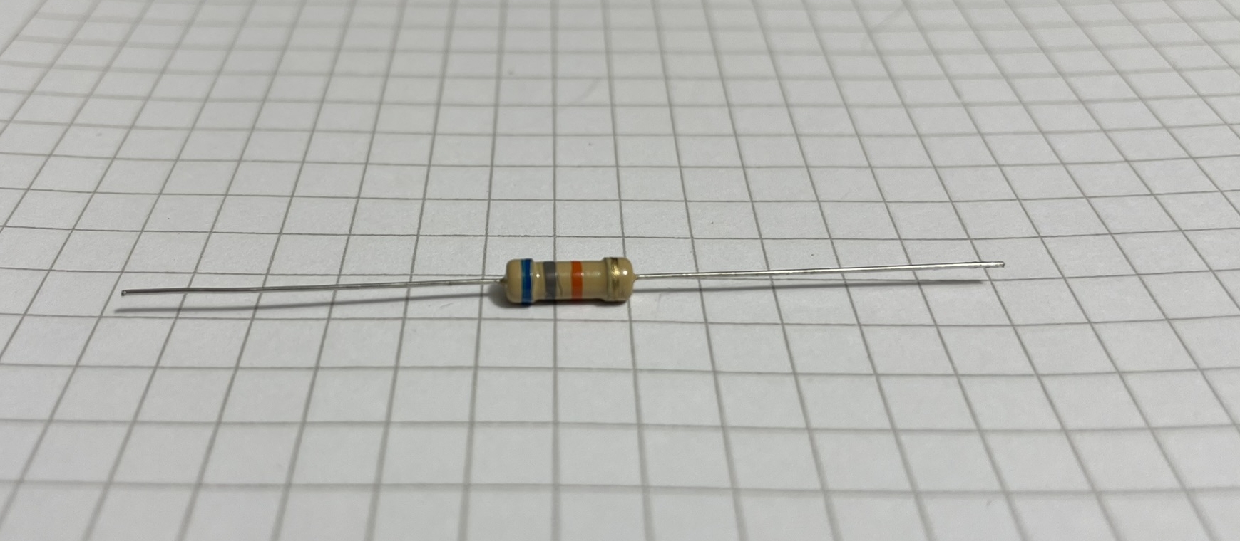
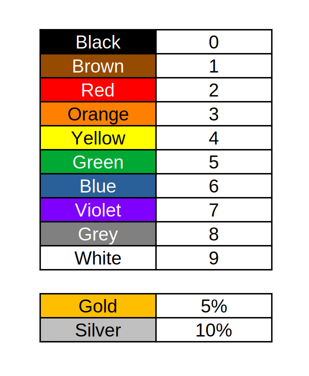
First image is the resistor we will decode the value of, and the second is a simplified coding table for resistor values.
We orient the resistor with the gold or silver band to the right.
Then from right-to-left we start reading the bands, and also writing its value.
- The first band on the right is the tolerance (maximum error on real-live-value). With this resistor that is gold, the most common value → 5%
- Second band is a multiplier. Simply put, the amount of zeros after the value, Orange → 000.
- Rest of the bands are single digit values by the colors in the table (still from right to left). Gray then Blue → 68.
So the resulting value is 68 000 5% → 68K Ohm resistor with 5% error margin.
Note: The tolerance is a quality thing. Most circuits function just fine with a 5% error margin and as a result, those became common, mass-produced and the cheapest we can get.
Wikipedia article with more information
What and were to buy
Summary: Choosing the Right Resistor
- Recap of Power Ratings (Watts).
- When to use Carbon Film vs. Metal Film.