Skip to content

Krakkus.com

Electronics

Menu
  • Home
  • Posts
  • About
  • Author
  • YouTube
Menu

DAC generator

    NOTE! The generator is one scroll down

    You want a dirt-cheap-super-simple digital-to-analog-converter? Then this is the tool for you!

    Enter the resistor values you have available and how many bit resolution you want your DAC to have, and hit the compute button. It will then search for the best possible combination of resistors.

    The result comes in four parts.

    1. Score: This is the total deviation from a perfect DAC. You can only compare scores within the same amount of bits.
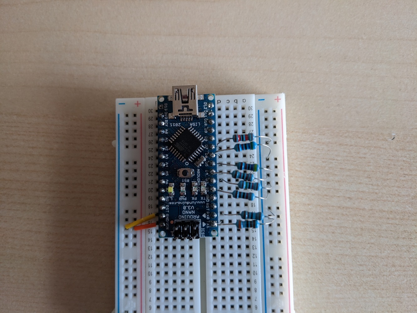
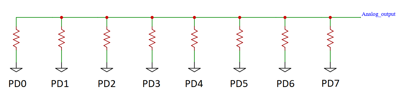
    2. Resistors: These are the resistor values you need for your DAC. Each resistor goes into a separate output PD0/digital 1 and up. The other ends of the resistors all go to the same place, the output!
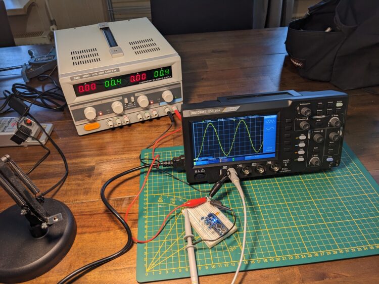
    3. Code: This is a demo sketch using your resistors. It will output a nice sine-wave for you.
    4. Graph: It shows a straight line like a perfect DAC would output and a not-so-straight line which your DAC will output.

    Have fun!

    Supporting images

    The actual generator

    Available Resistor Values


    Current Iteration:

    -

    Best Score:

    -

    Resistors:


    Piece of Code:


    Graph:

    Leave a Reply Cancel reply

    Your email address will not be published. Required fields are marked *

    Other Posts

    • Hacking a DC to DC converter

      Hacking a DC to DC converter

      Introduction This is a follow-up of a proof of concept I made two months ago. I used an Arduino based DAC (8 bit 8 resistor) and an op-amp to create a signal...
    • How to add dead time to PWM

      How to add dead time to PWM

      There are situations where you absolutely want to avoid signals overlapping one another. This is when you get introduced to the term dead-time. I will give you an example of a circuit...
    • Ten ways to drive a MOSFET, with examples

      Ten ways to drive a MOSFET, with examples

      These are a couple of circuits that can drive a MOSFET. Each of them has their own pros and cons, so whether or not they are useful is highly dependent of what...
    • How to make an op-amp output PWM with duty-cycle control?

      How to make an op-amp output PWM with duty-cycle control?

      We can use a generic op-amp like the LM4562NA. We build an oscillator from the first op-amp in the IC. This produces a triangle-wave. We feed this wave into the second op-amp....
    • How does an op-amp work?

      How does an op-amp work?

      Op-amp is short for operational-amplifier. You can use it as a comparator, buffer a signal, or amplify a signal. These are some op-amps I have; they are the LM358 and the LM4562....

    Tools

    • DAC generator
    • Ohms law calculator
    • Inductor calculator
    • Where to get MOSFETs?
    ©2023 Krakkus.com | Design: Newspaperly WordPress Theme