A resistor divider creates a voltage in between the top voltage and ground. In this post I try to explain why that is.
TLDR: It is a result of current going into the midpoint from the top resistor vs current going out through the bottom one. It is because of Ohms law and its linear characteristics that a stable voltage point exists somewhere in the middle.
The experiment
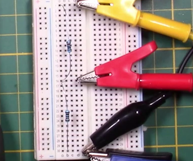
These are two 100K resistors in series. Also, two multi-meters to measure the total and the in-between voltage.
Because these resistors are equal, of any voltage applied to them, we will see half the voltage in-between.

Now we apply voltage. We can actually see the in-between voltage follow the main voltage
Adding capacitance
The in-between point also has some capacitance because of the metal legs of the resistors.
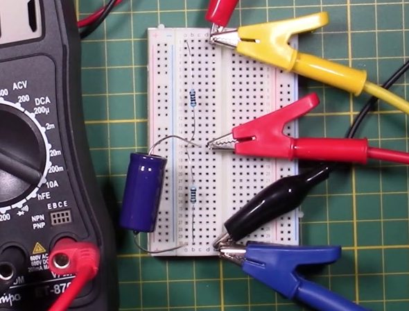
Adding a little capacitance does not change the circuit much, it only makes it slower
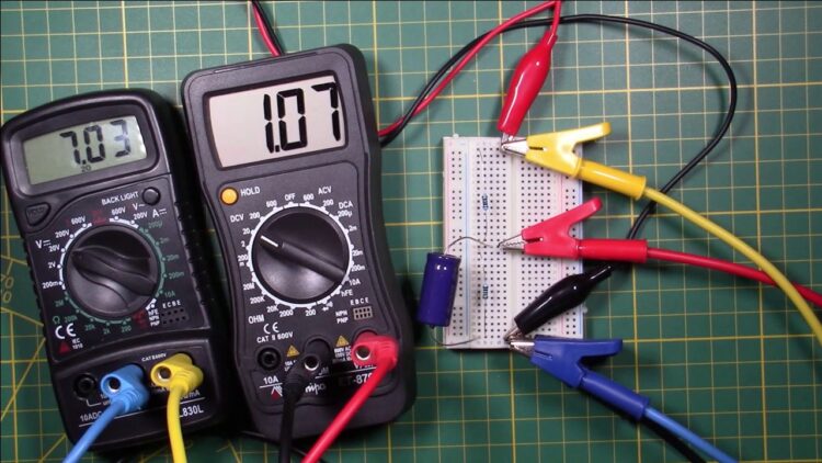
As I increase the voltage, you can see the in-between voltage rising too, but not fast enough. I eventually set the main voltage to 7.

As you can see the in-between voltage finally reaches the half-way voltage, but not before slowing down a lot.
Whats going on?
Current = Voltage / Resistance
It’s Ohm law!
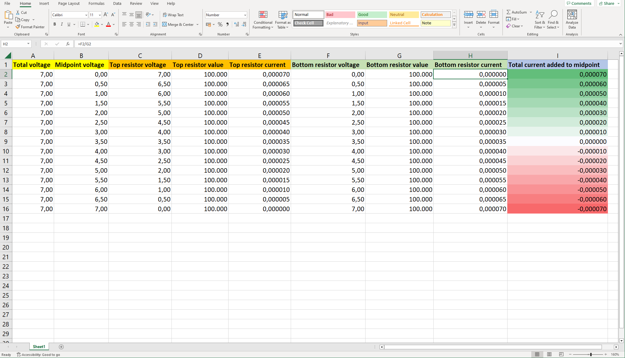
I made an excel file to calculate the currents going through both resistors at any possible midpoint voltage
When this circuit starts (top row in the chart), the in-between point is a zero volts.
The top resistor therefore takes the full voltage and delivers 7V / 100.000R = 0.000070A -> 70 uA to the midpoint.
The bottom resistor does not take any voltage and therefore does not remove any current from the midpoint.
So a total current of 70 uA is added to the midpoint, adding current means voltage going up.
In the next row we see the midpoint-voltage 0.5V higher, the current added by the top resistor decreases while the bottom resistor start taking current away to ground.
As you can see in the right-most column, The total current going in is equal to the current going out at 3.5V midpoint, this is when the voltage stabilizes.