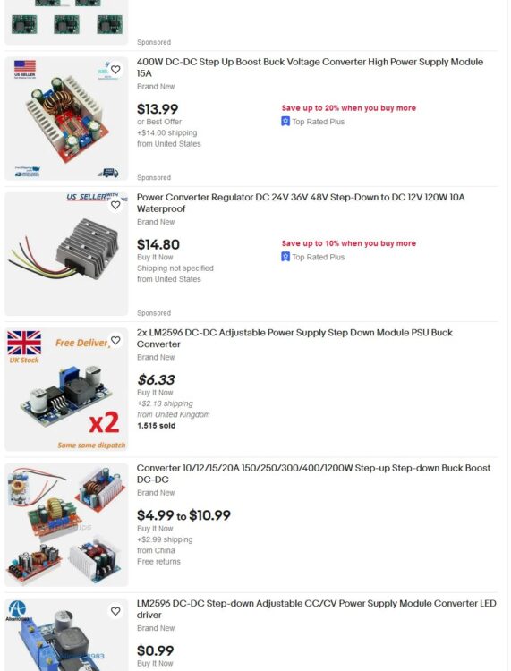
You can buy great and cheap DC-to-DC converters on the internet. Wouldn’t it be great to control them remotely, well, it turns out we can!
Introduction
This is a follow-up of a proof of concept I made two months ago. I used an Arduino based DAC (8 bit 8 resistor) and an op-amp to create a signal that could control the output of an eBay buck converter.
This time, I will make a simpler circuit that will just accept a PWM signal in order to control the converter. That makes it much more user-friendly than the previous circuit.
I will also show you each step on the way, so you can create this yourself if you want.
Table of Contents
- Introduction
- Targeting the feedback pin
- What does it do?
- Why not the potentiometers?
- What do we want to do?
- Full throttle by default
- Adding wires
- Adding current
- How much current do we need to add?
- Schematic
- Only push, no pull
- Building the circuit
- Testing the circuit
- Showing the board
- Room for improvement
- Where can we use this?
- Video
Targeting the feedback pin
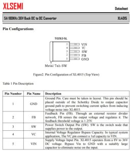
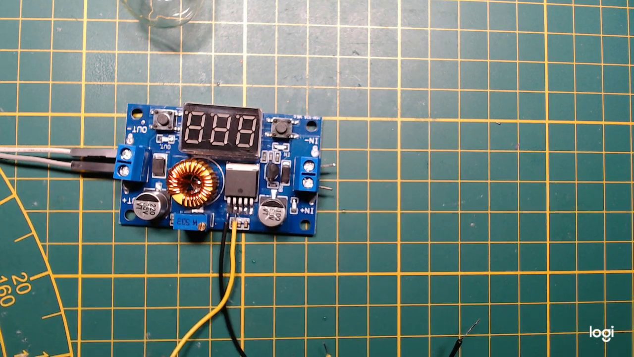
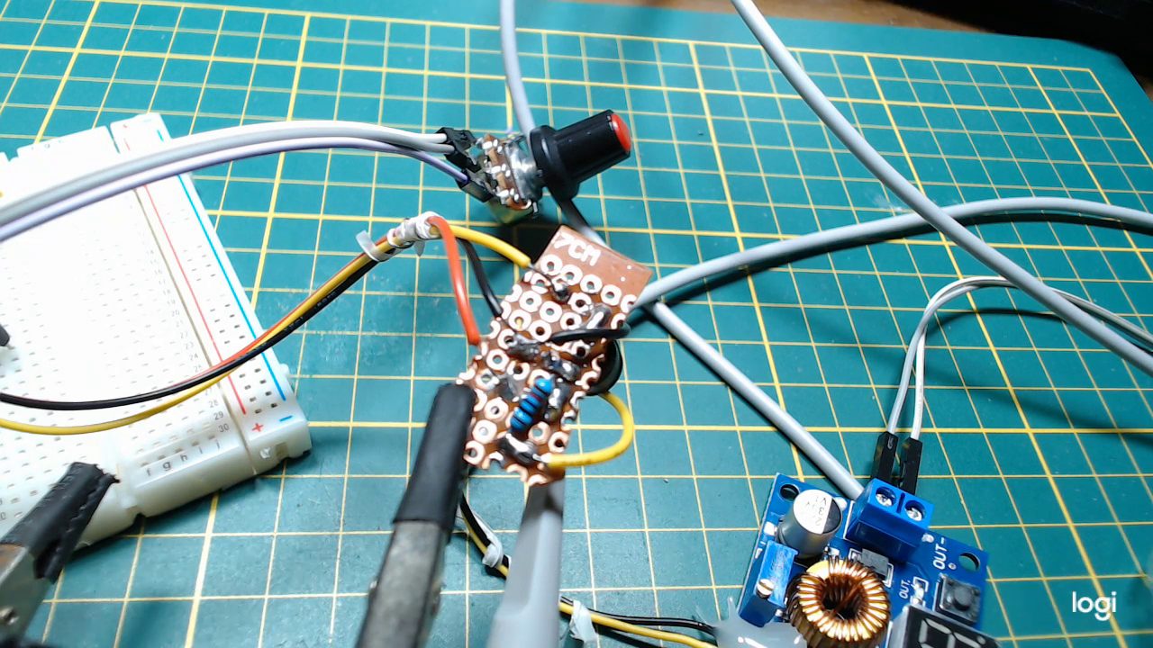
Almost all the eBay converters use a controller IC like the one in the picture above. And all these IC’s have something in common, a feedback pin. This is why I chose to create a generic solution around this pin. Just grab a converter from eBay, apply this technique, and you are good to go.
What does it do?
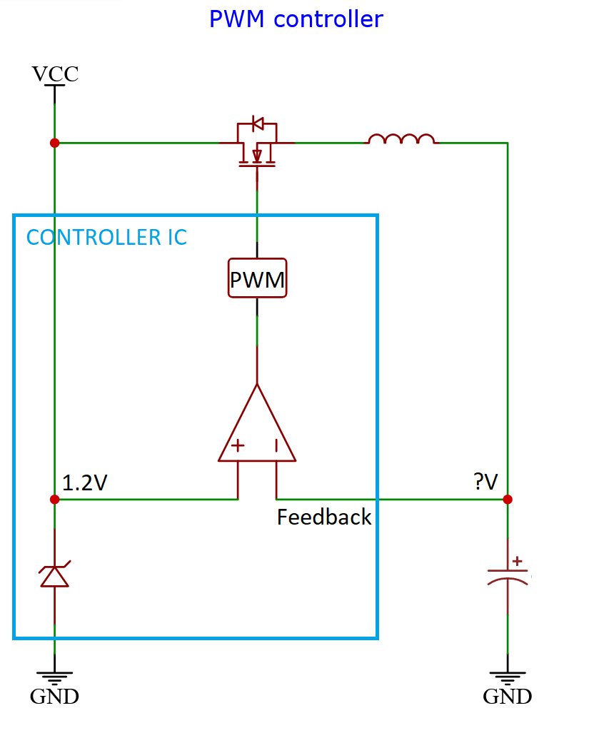
The controller IC is outputting a constant PWM signal to control the MOSFET that switches the input power, so current can flow to the output side.
Inside the controller IC is a stable voltage source, probably a zener-diode, that outputs a fixed voltage. Its value can be anything, but usually very low, like 1 or 2 volts.
At the same time, the IC is constantly comparing the output voltage to the fixed voltage and makes a decision.
Is the output higher than the internal reference voltage? Decrease the PWM duty cycle!
And if the output voltage is lower? Increase the duty cycle!
This all happens really fast, so the output voltage remains quite stable.
The result of this is that the voltage at the feedback pin is the same as the reference voltage, even though they or not connected, it’s all done by the actions of the IC.
All of this would only give us an output voltage equal to whatever the reference voltage is. Fortunately, we are allowed to feed the feedback pin anything we like.
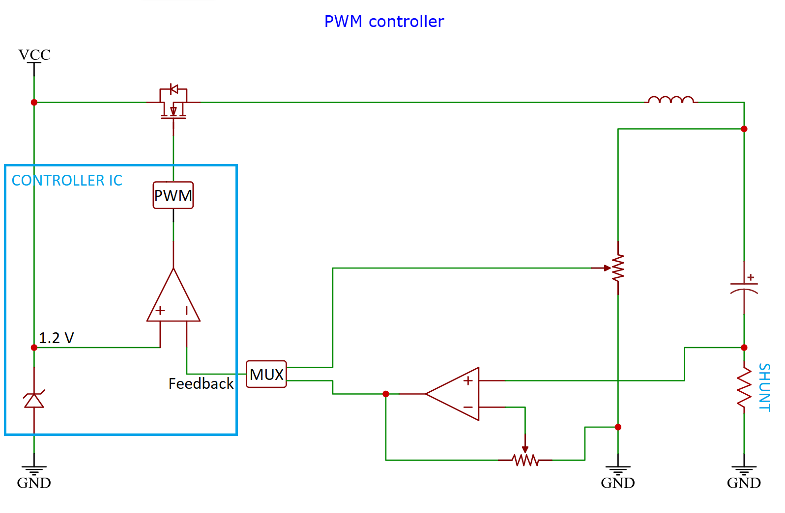
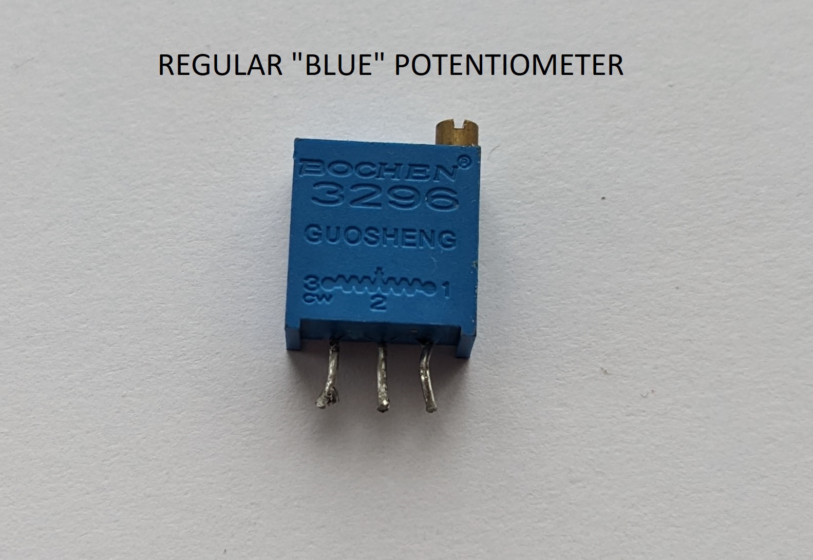
The common thing to do when designing a generic DC-converter, is use a potentiometer, so we can feed it a fraction of the output voltage, leading to a higher output voltage we can control ourselves.
And then do the same for current. And then multiplex both signals into a single one.
Why not the potentiometers?
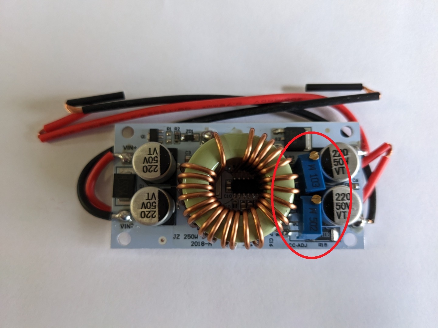
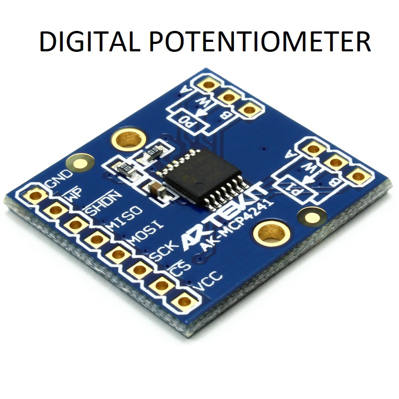
Replacing the potentiometers on the converters with a digital variant seemed to me like the obvious solution, giving me instant control of the device.
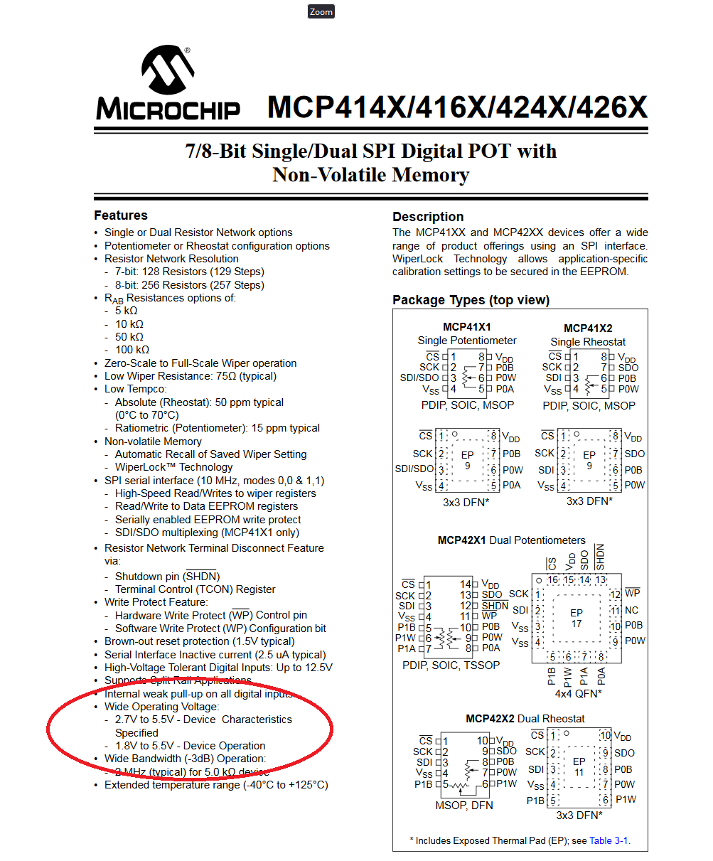
These digital potentiometers however are very limited in the voltage they can handle, so not a very generic solution for me.
Greatscott on Youtube did a video on that approach.
What do we want to do?
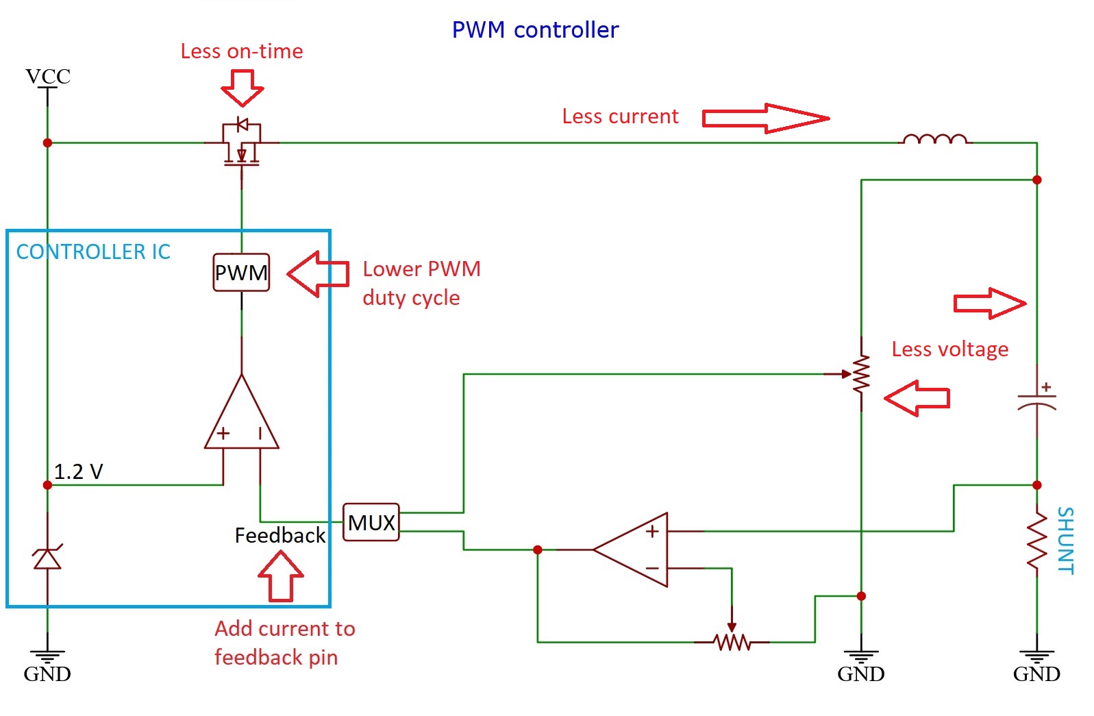
In order to control the device, we need to influence the feedback pin. The voltage on the pin will always be the same as a result of the controller IC’s hard work. But we can change how hard is has to work to keep it at that level.
If we add current to the pin for example, the controller needs to remove current to keep the voltage at the same level, it does that by lowering the PWM signal, leading to less voltage on the resistor network.
Full throttle by default
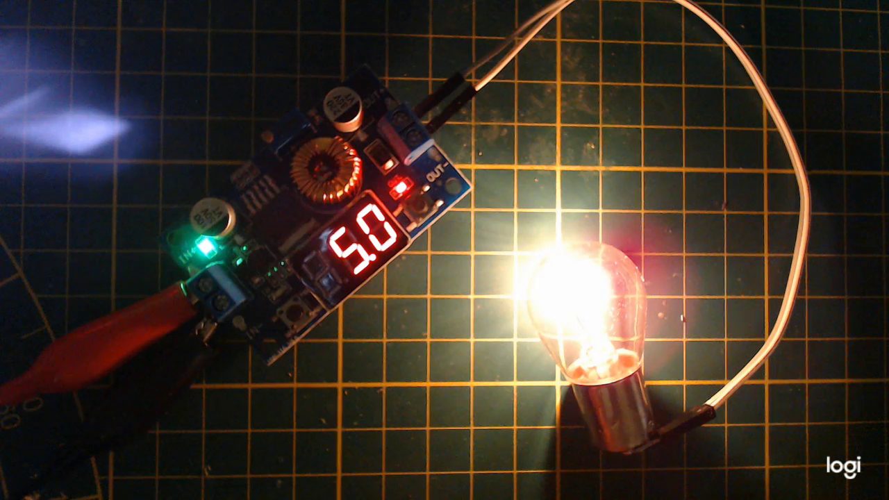
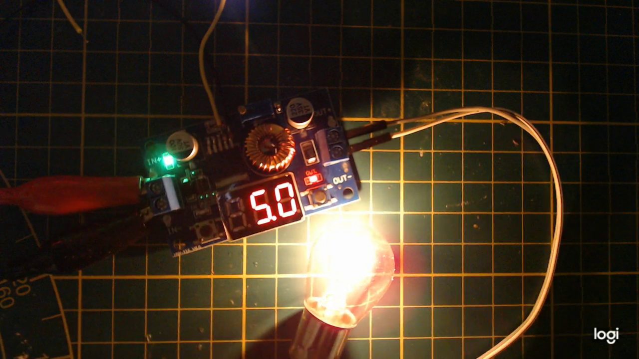
The first thing we need to do is set up the converter to output whatever we want at maximum.
For me this is 5 volts because otherwise the lamp would be too bright for me. But I can image it to be 13 volts for charging a car battery for example.

Please note that always-on is not a good practice in general, but this is a device that does that by design already, and we are simply adding the option to dial it down. But to be fair, we could turn this upside-down without too much trouble.
The always-on method however allows us to set a very precise upper limit, even when the add-on-circuit fails. So I’ll go for that.
Adding wires
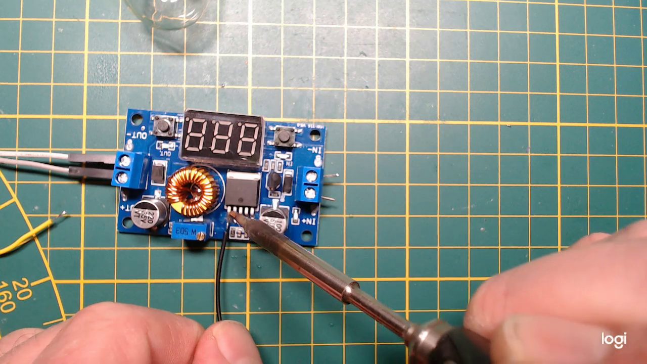
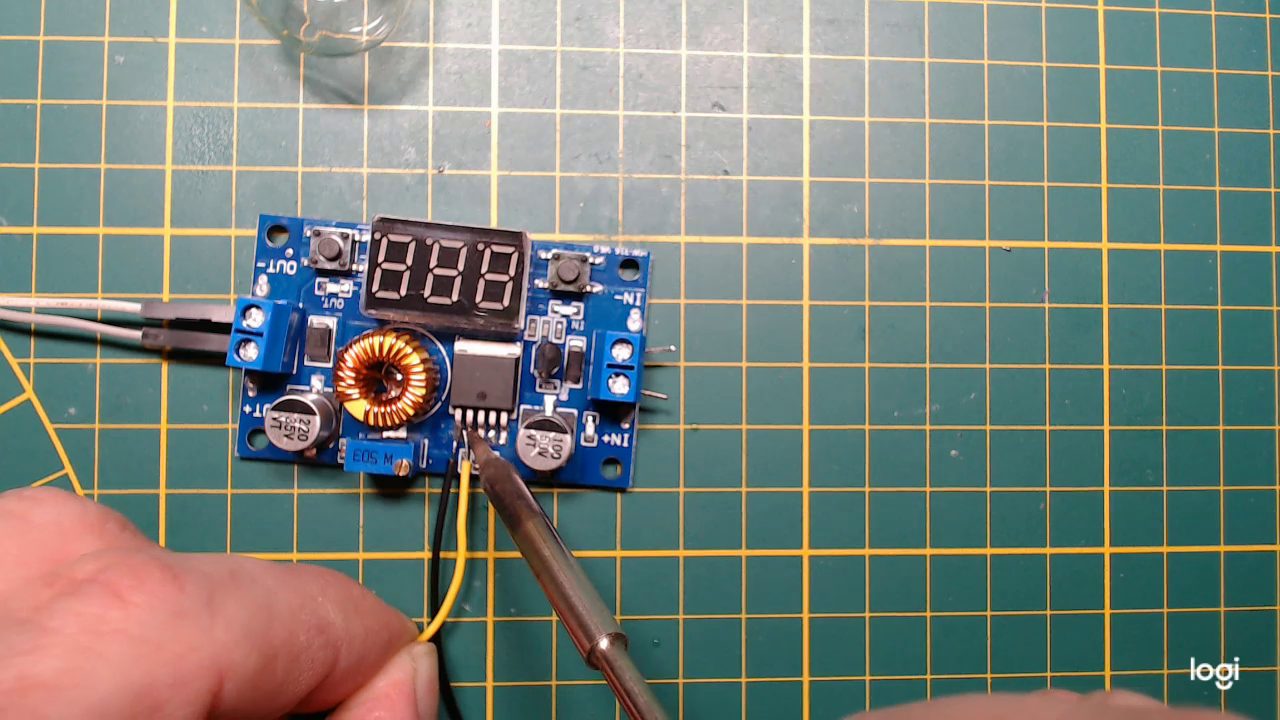
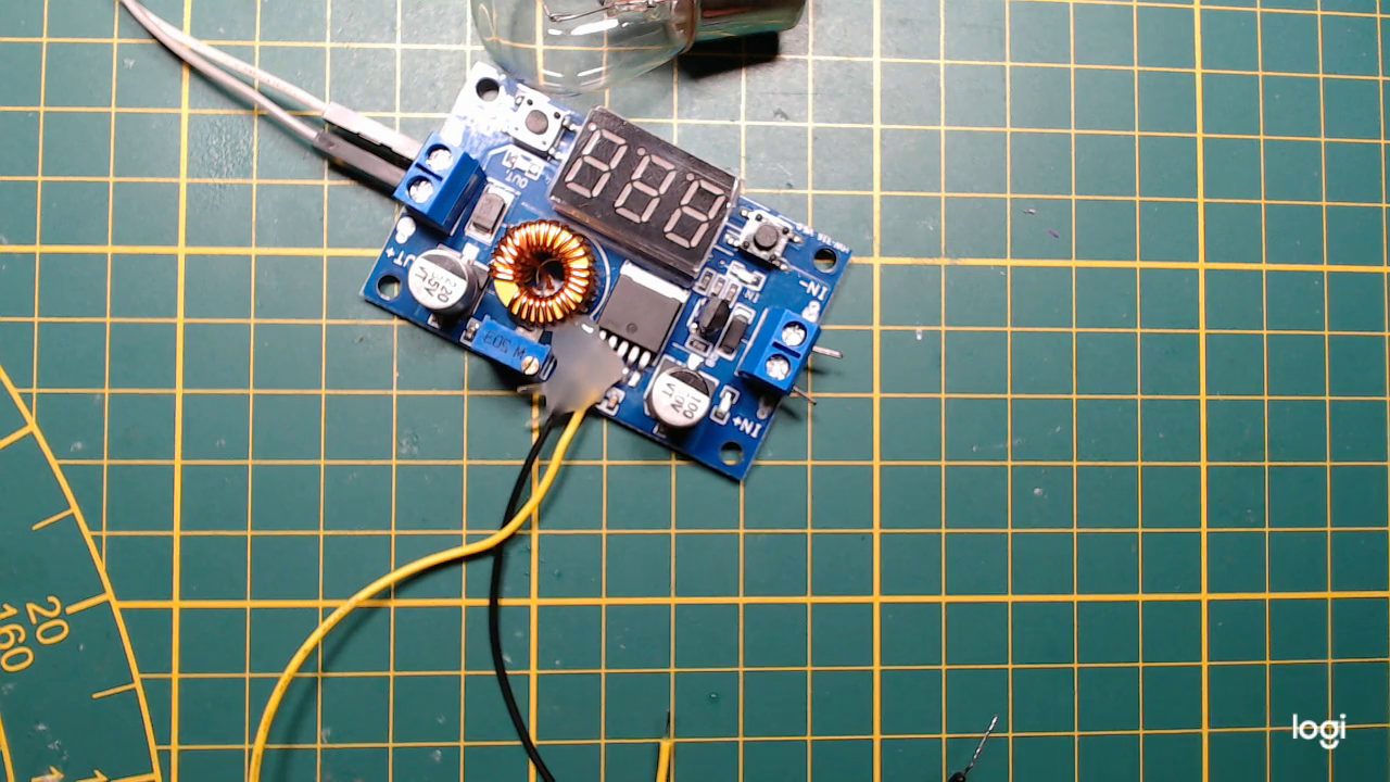
To control the device, I have to solder a wire to the feedback pin.
And also one tho the ground of the IC, because otherwise me signal will be meaningless.
Adding current
Because the device is full-on-by-default, we only need to add current to the feedback pin to control it. An off-by-default device would be controlled by removing current.
How much current do we need to add?
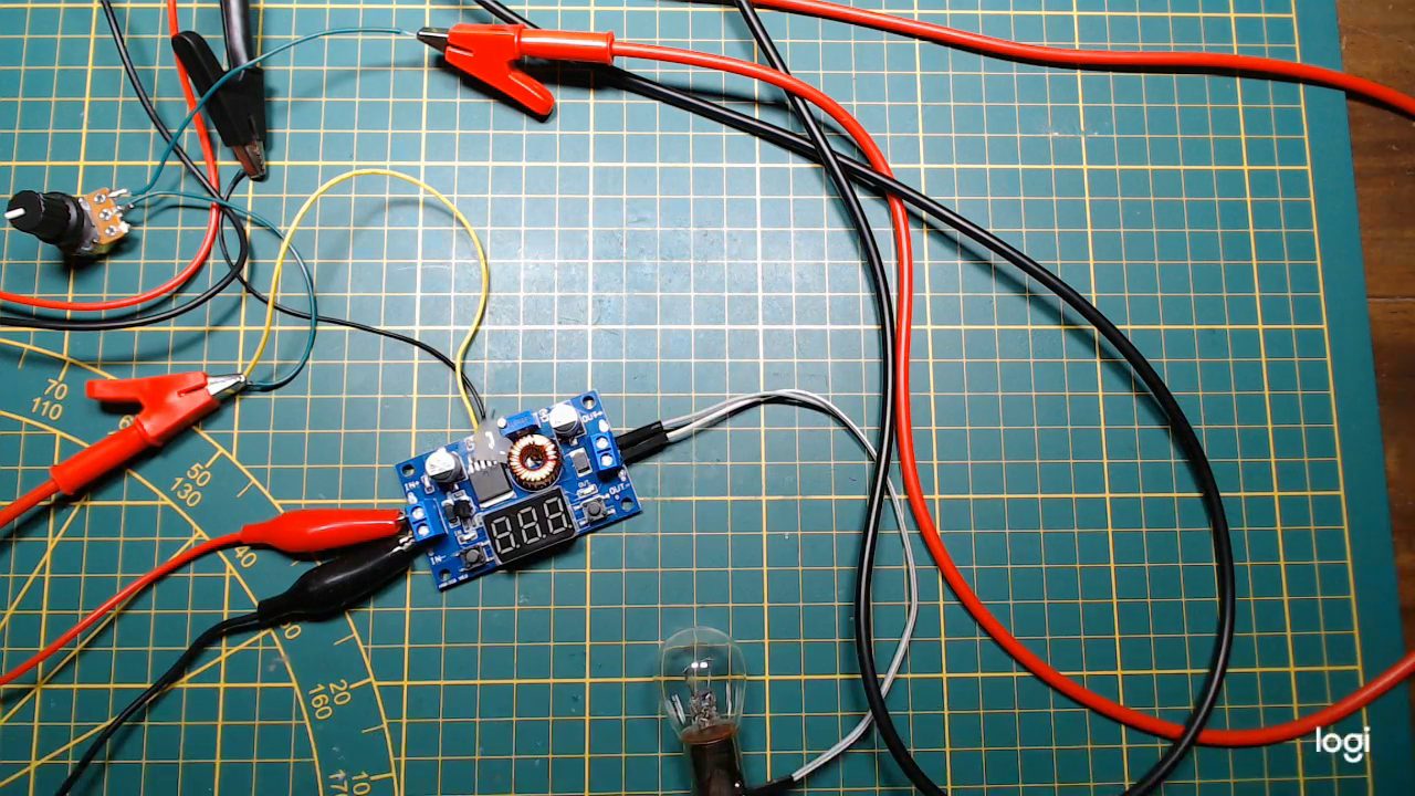

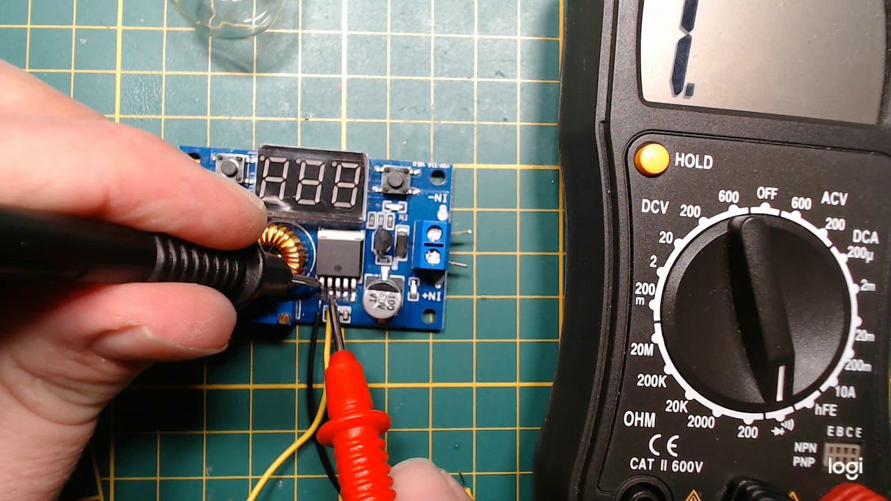
Now I am going to use one side of a potentiometer, so I can connect 5 volts through a variable resistor in order to dump current into the feedback pin. I want to know what resistor to use in order to completely turn off the device.
I turned out to be 3.95 kilo ohm.
For extra science points, I will calculate the needed current for this, so we can potentially control it from any other voltage as well.
I = V/R
I = 5 / 3950 = 1.2 milli-amp
Luckily for me, I did the measurement with the same voltage as I will use to control it automatically, so I only need to know the resistor value.
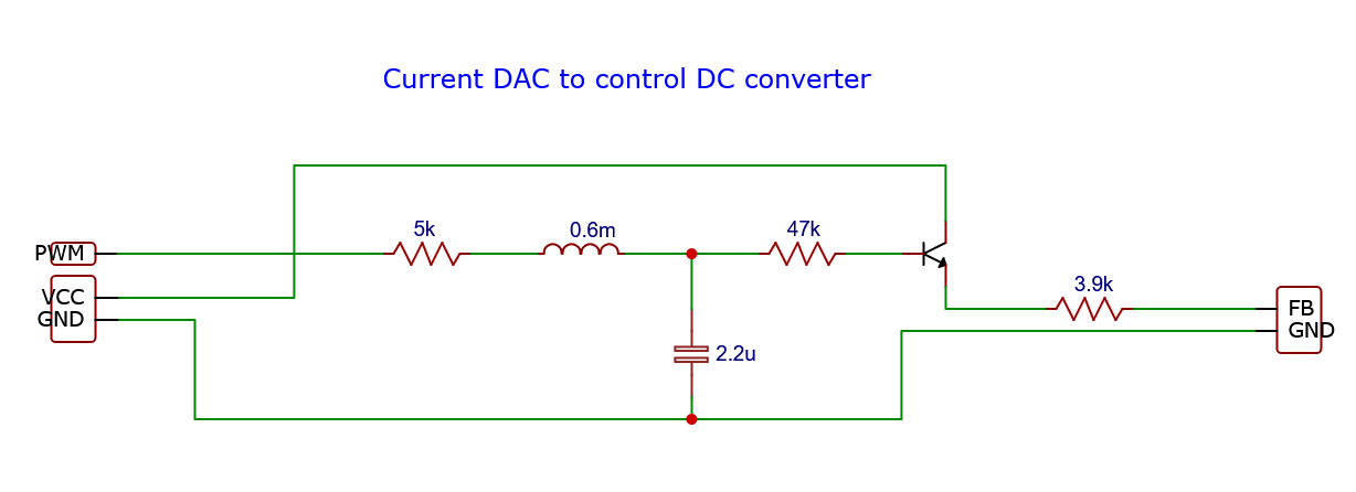
Schematic
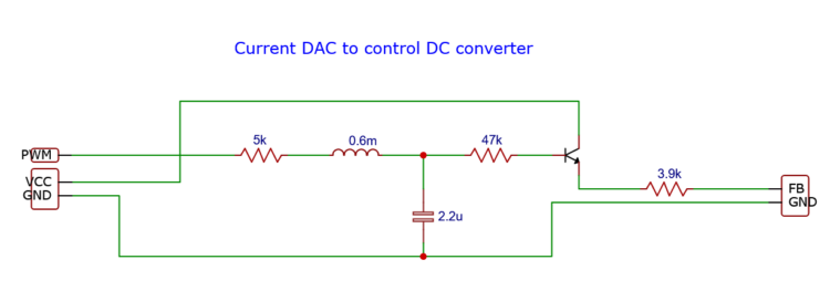
Well, this is the circuit. From left to right, the PWM signal first goes through a 5k resistor to limit the current stress on whatever we use to create the signal.
Then we have an inductor capacitor pair to smooth the square wave out.
Next we want to amplify the signal but not drain the capacitor too much, a resistor with a transistor follows.
And because I threw in a random NPN transistor with unknown gain, I choose to limit the current by a resistor slightly lower than the value we obtained in our test.
This resistor later turned out to be not low enough, but I fixed that.
Finally, the signal is sent to the feedback pin and the ground is shared with both the circuit and the sender of the PWM signal.
Only push, no pull
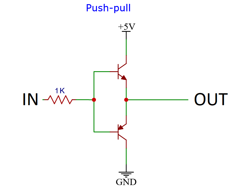
Normally, when amplifying a PWM signal, we would implement a push-pull configuration to send a signal to the feedback pin. But since we are only interested in adding current we would throw away a lot of resolution because it could also remove current, and also add a risk off driving the target voltage or current above the desired limit we just set when the PWM signal’s duty cycle gets too low or even off.
Building the circuit
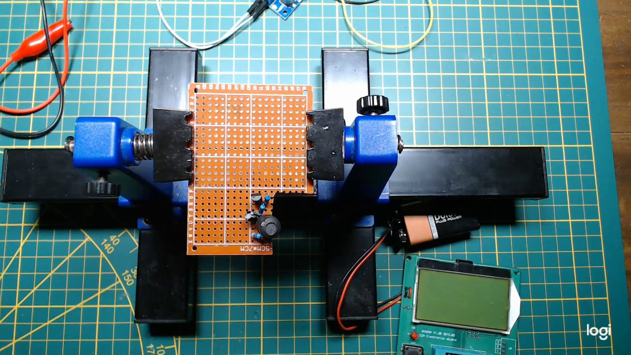

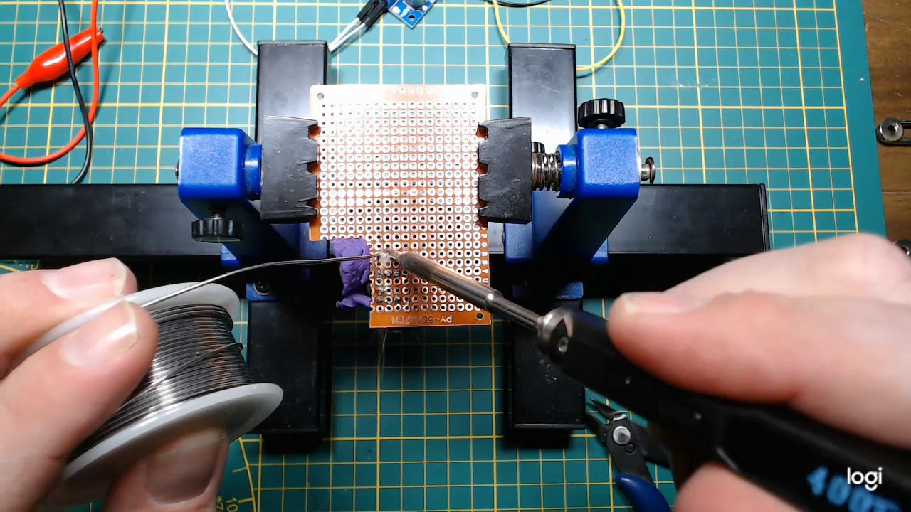
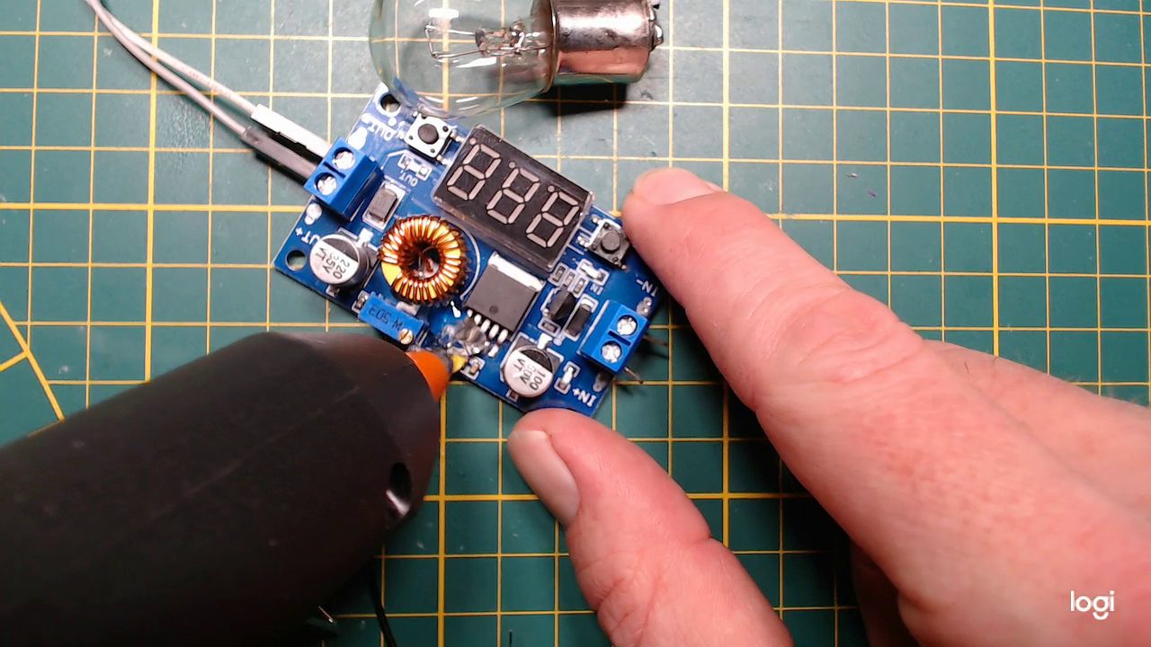
Building the circuit went quite well. The components are really close together, but that did not create any problem.
I used some clay to keep all the components stuck to the board while soldering the bottom side.
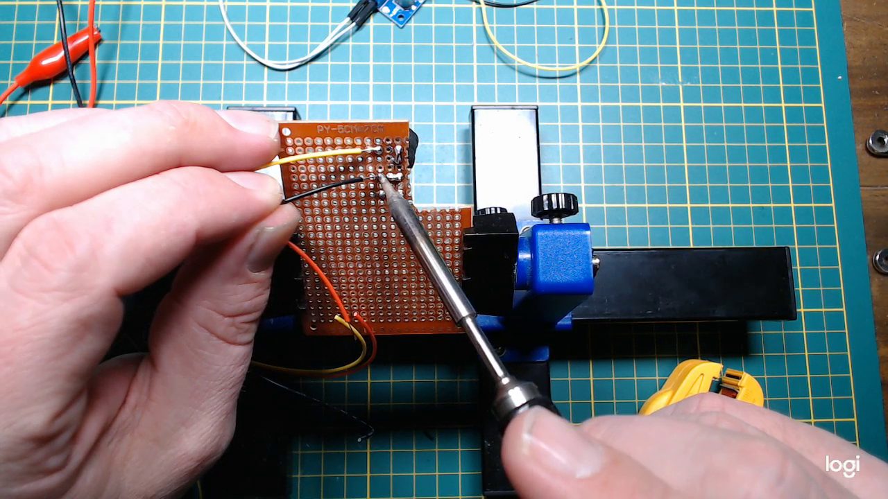
When that is done I removed the clay and started working on bridging connections, wire and such.
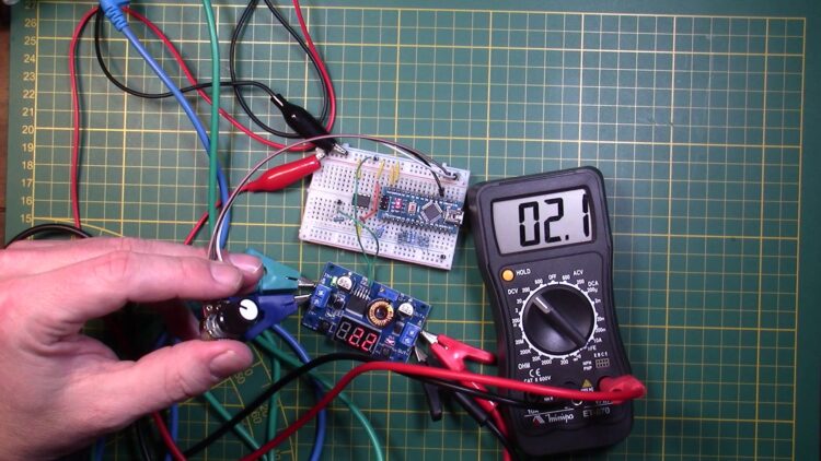
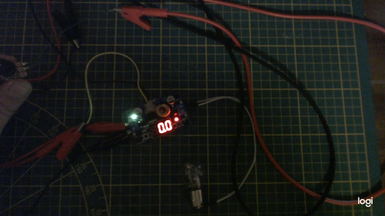
Testing the circuit
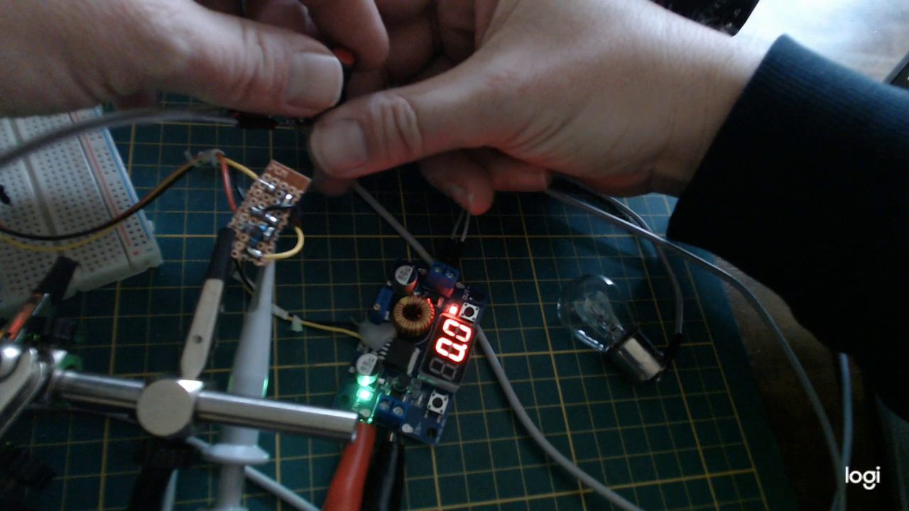
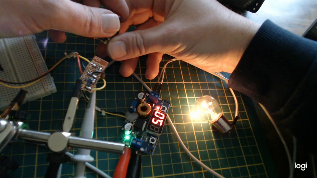
While testing, I discovered that I was 0.1V away from being able to turn the converter off completely. To fix this, I would have to be able to provide a small bit of extra current.
I decided not to replace the resistor, but solder one in parallel to the bottom of the circuit-board.
Showing the board

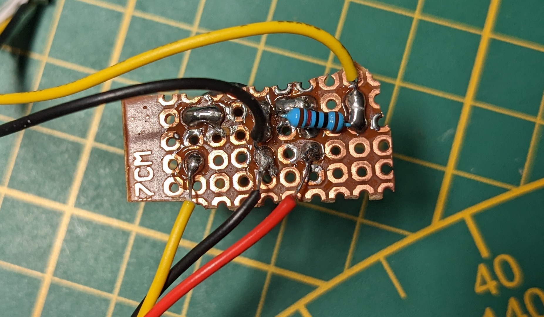
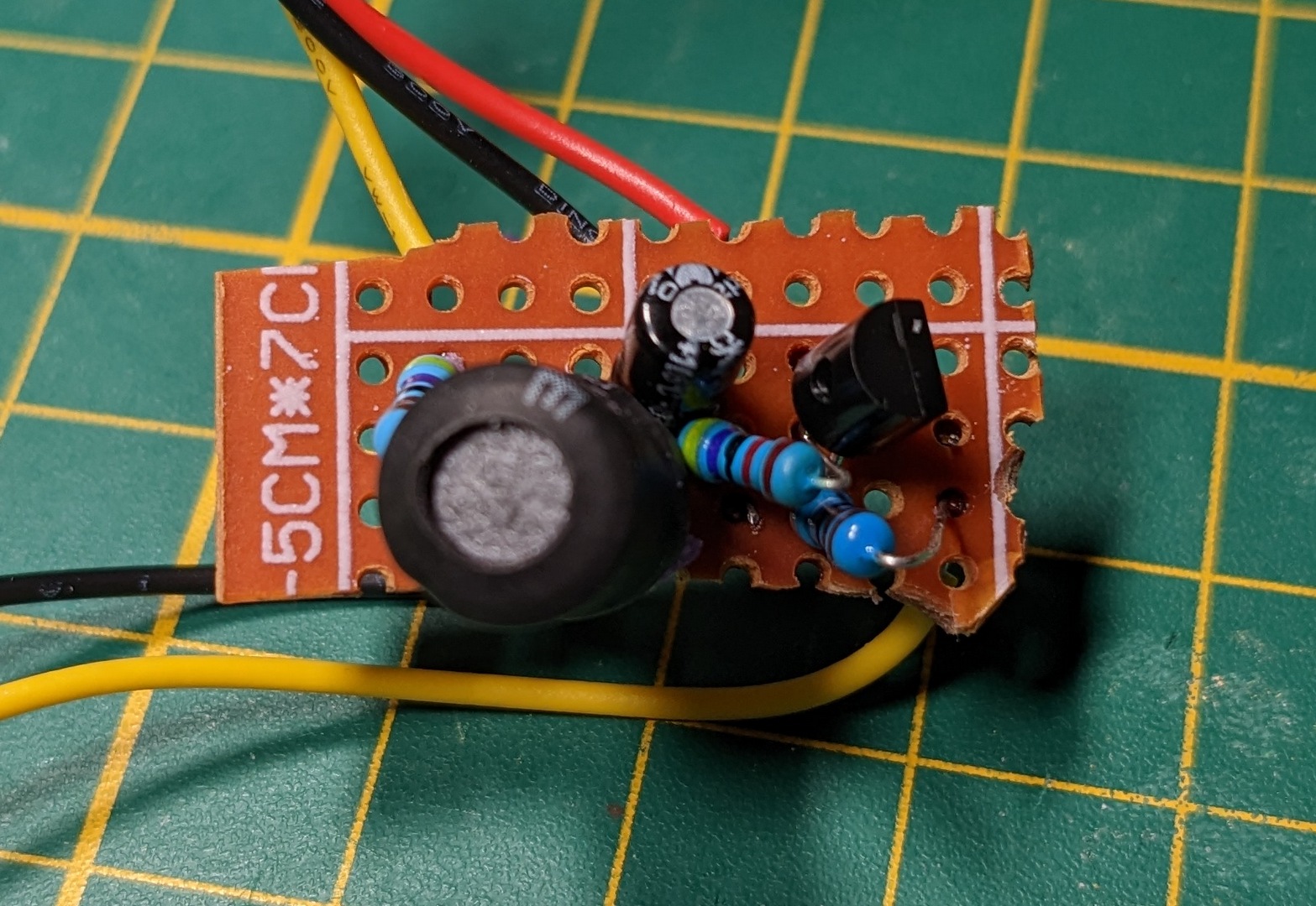
This is the working prototype, without all the probes, meters and wires. It is 3 centimeters long and 1 centimeter wide and costs less than a dollar/euro to make on materials.
Room for improvement
This circuit uses a fairly large inductor-capacitor pair in order to keep voltage ripple as low as possible. But this makes the circuit also very slow to react.
In order to fix this, we should increase our PWM frequency. We can do this by setting the multiplier to 1 instead of ?. And we can also give up some timer resolution to get the frequency up even more.
TCCR1B = TCCR1B & 0b11111000 | 0x01;
OCR1A = 100;
Where can we use this?
Obviously there is a reason for me to be developing this technique.
I believe these converters on eBay have a huge potential if we can set them free and control them with an outside signal. We can do all sorts of power-related automation, which is very useful in the energy transition we are going through.
It also sets us free from the proprietary solutions that are available but very expensive.
I really think we need this in our future. Let me give you some examples.
MPPT for solar panels
Solar panels have a continually changing optimal voltage they operate on. Adding a voltage and current probe together with one of a few algorithms available, you can steer a converter to extract just at that voltage from the panel.
Grid tie inverter with limiter
If your solar panels charge batteries, you can have the batteries power a grid-tied-inverter. But not full power, just enough to keep your electricity meter from running in either direction, throughout the night if possible.
Just read out your electricity meter and have a converter control the power flow.
Energy automation in general
I think energy automation will become a really useful tool in the future. Some things will need a hard switch, like appliances or a charging car, and others can be tuned with this solution.
And I will continue to investigate solutions that allow us to do just that without needing to sell a limb.
Hi,
What is the value of the inductor you use ? On the schematics I see “0.6m”. Do you mean 0.6 milli-henry = 600 µH ?