There are situations where you absolutely want to avoid signals overlapping one another. This is when you get introduced to the term dead time. I will give you an example of a circuit that needs dead time and I will show you how to create it, and how it works.
Table of Contents
An example
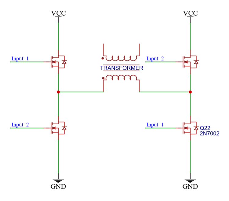
This is a classic H-bridge circuit. Four MOSFETs steer the direction and amount of current through a transformer.
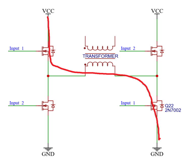
If inputs_1 are both active, then current goes from left to right.
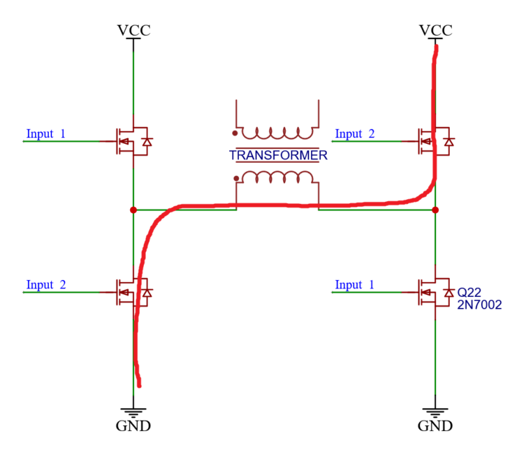
And if inputs_2 are both active the flow goes from right to left.
Most of the times we want to control the inputs with a PWM signal. So we create one and send it to the MOSFETs on input_1.
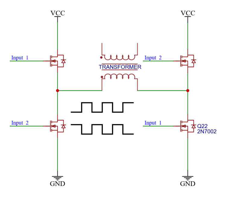
And the other inputs need to be on at times when the first are off, so we invert the PWM and send that to inputs_2.
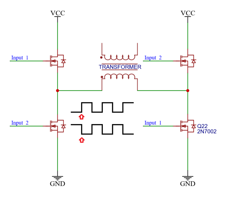
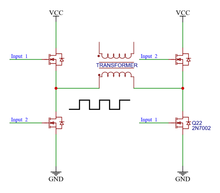
But there is a problem! At the rise and fall of the signals, both signals momentarily are high at the same time.
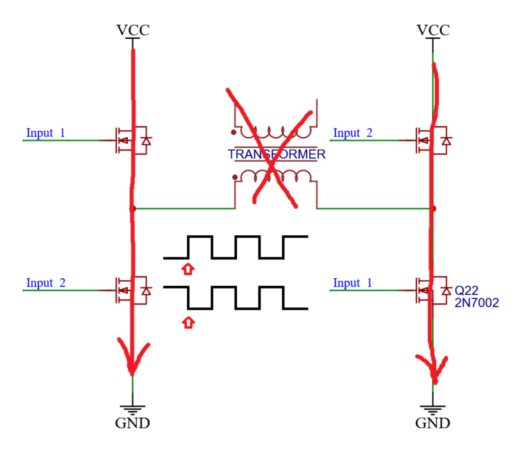
And thus all the MOSFETs are on for a brief moment. And instead of current going through the load in the center; we have two shorts to ground, and now our house is on fire.
The solution is dead time
In order to fix this, I made a circuit that takes an PWM signal as input, and then creates two new signals, that can never overlap.
I made this simulation on everycircuit.
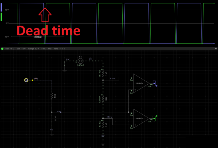
A you can see in the signal output of this simulation, there is an actual space between the two.
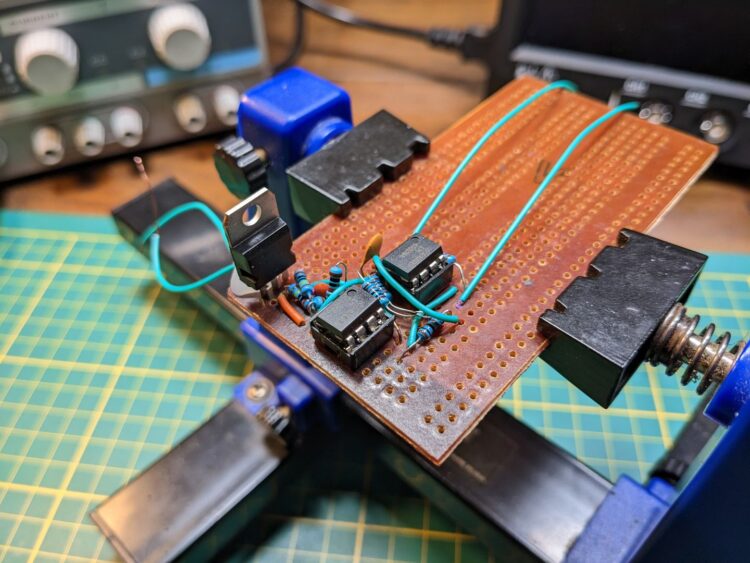
This is the prototype of the circuit.
Because of my ‘unique’ way of routing and organizing the board, I will use the schematics for explaining the circuit later on.

The underside of the board 🙂
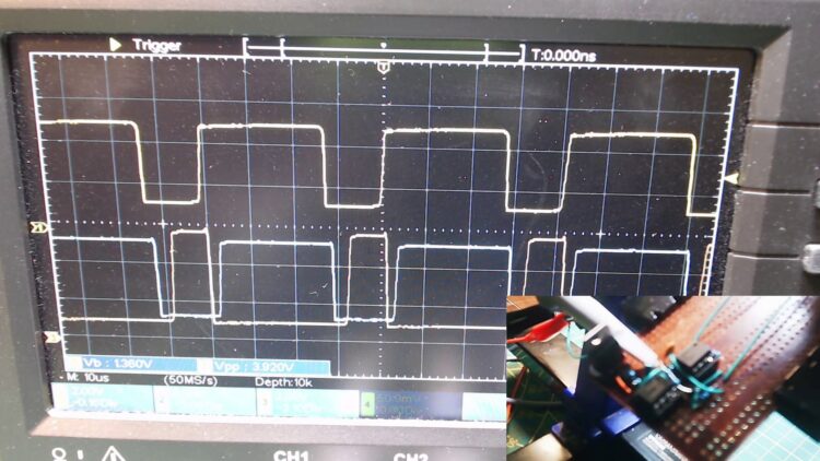
And then I connected my oscilloscope, to see if the thing actually worked.
The top signal is the input signal. It is not 50% duty cycle as it should be, but good enough for what I am trying to build, which is a DC converter.
I have made the oscilloscope overlap both output signals, so we can see whether or not they overlap. And I am happy to see that they don’t.
Explanation
I drew these circuits with Easyeda.
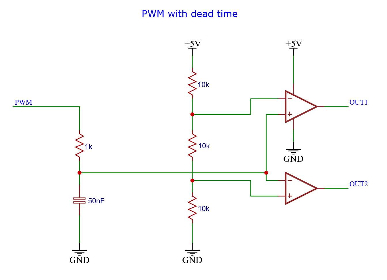
This is the actual schematic of the circuit.
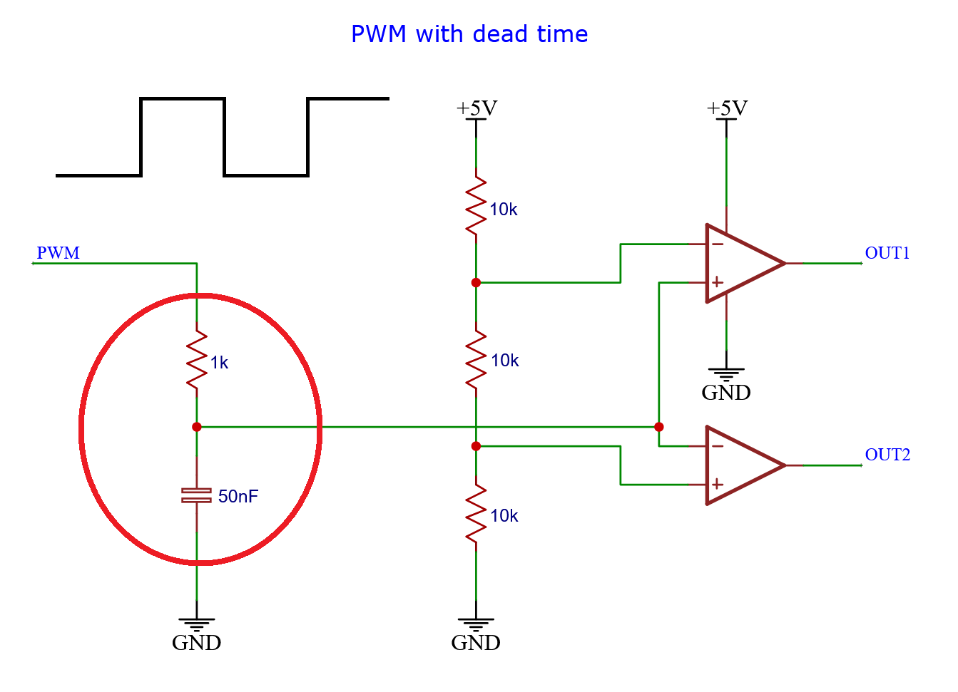
At the left side we have a resistor capacitor pair.
And we have the PWM signal coming in.
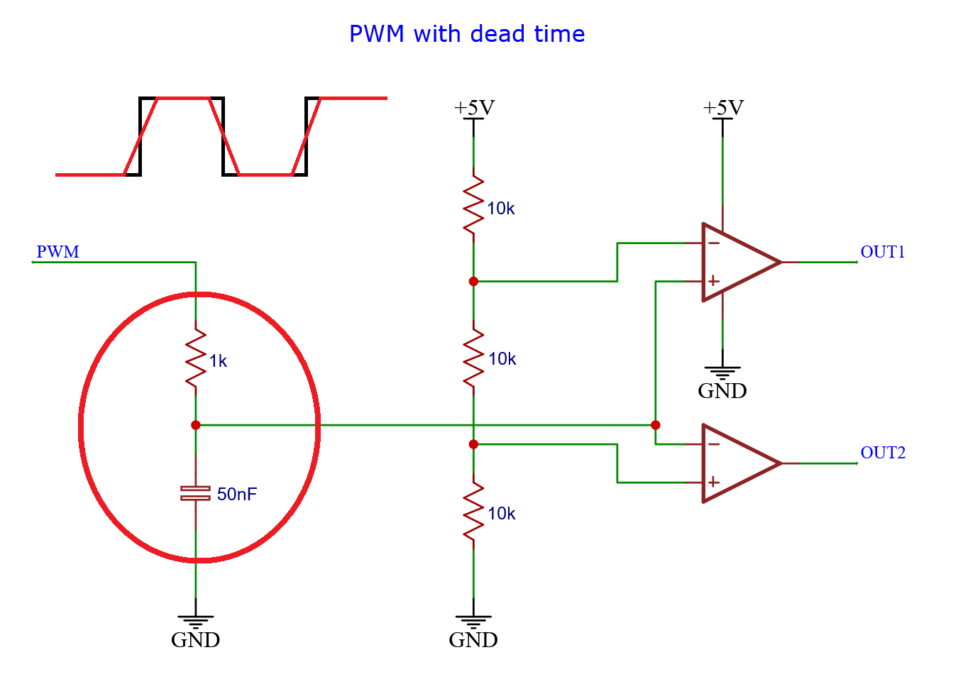
The PWM signal has to charge and discharge the capacitor through the resistor. This cause the rises and fall of the signal to slow down considerable.
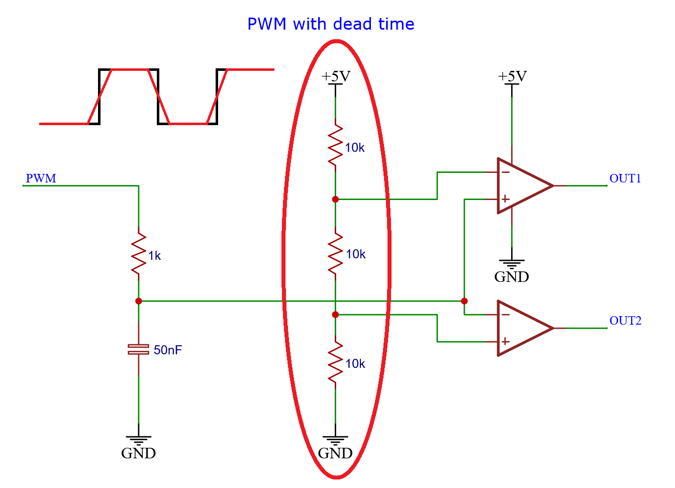
Then there is the resistor divider in the center of the circuit.
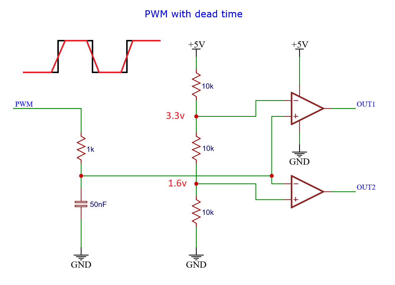
It creates two voltages which are compared against the slowed-down version of the input signal.
When the input signal is below 1.6 volts, the output_1 signal is low and the output_2 signal is high.
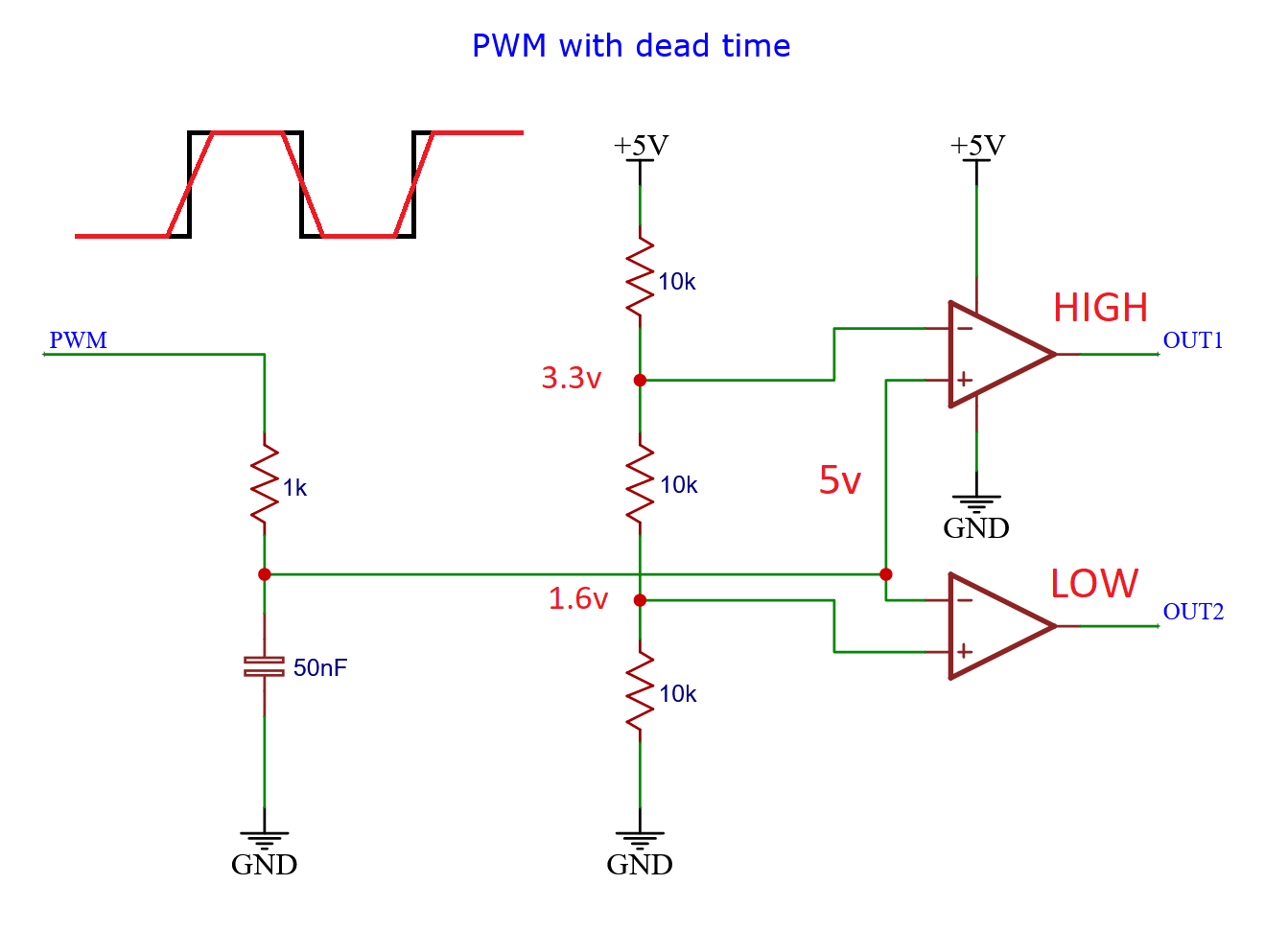
At the other end above 3.3 volts, the output_1 signal is high and the output_2 signal is low.
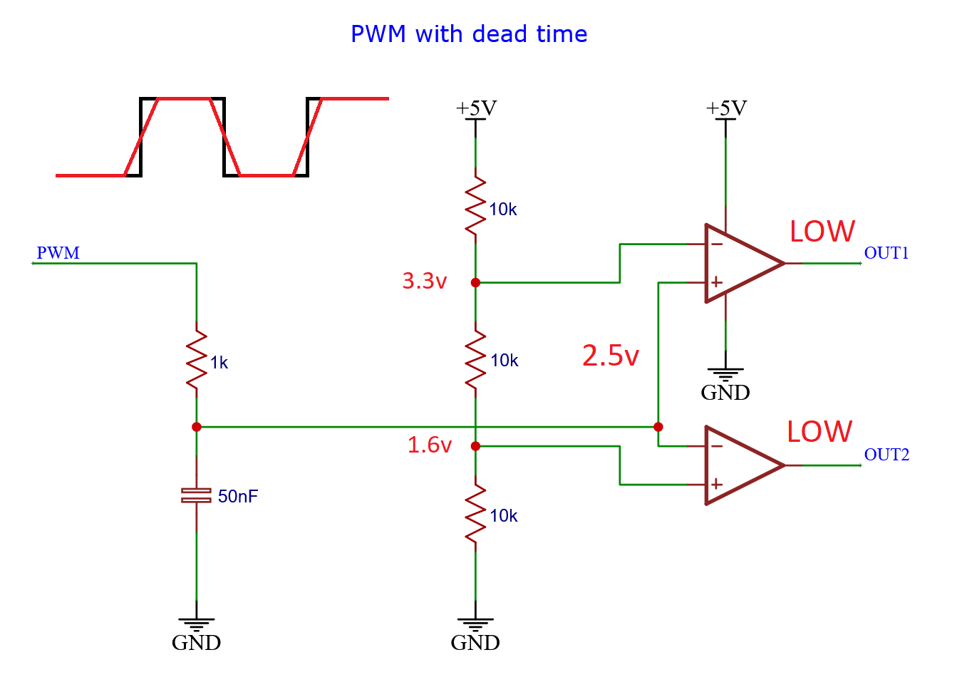
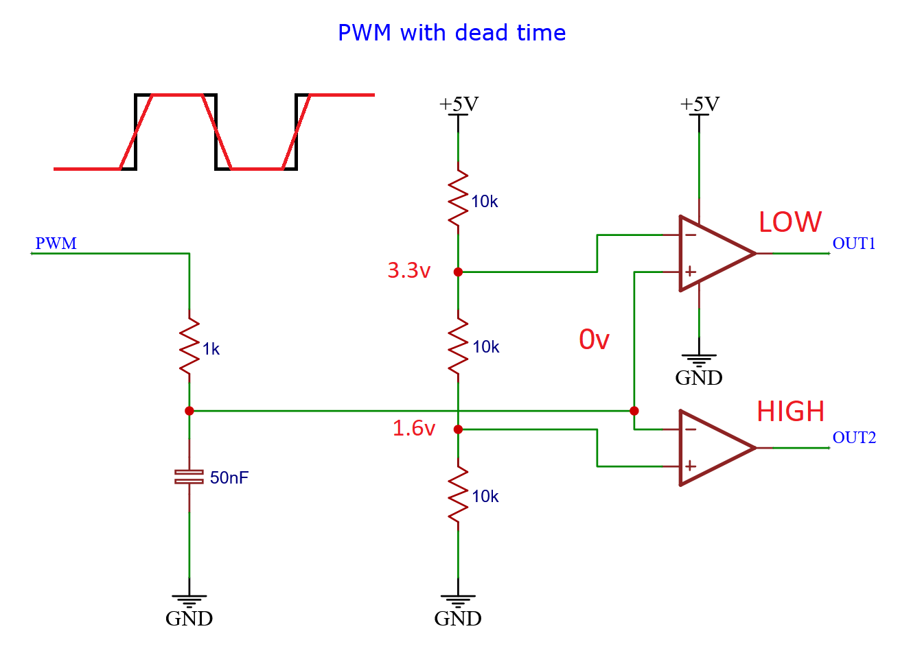
But the signal always has to travel through the region in the middle, between 1.6 volts and 3.3 volts. And in that region, both signals are low.
Video about dead time
I made this article into a video.