Skip to content

Krakkus.com

Electronics

Menu
  • Home
  • Posts
  • About
  • Author
  • YouTube
Menu

How to drive a relay from a digital pin, two solutions

Posted on November 24, 2022

The first is by using an NPN-transistor, and the second a N-channel-MOSFET. Both circuits are pretty much the same otherwise.

NPN transistor

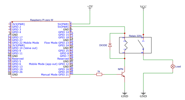
Using a transistor is the cheapest and fail proof way of doing this. Setting a output pin high on your CPU sends a resistor limited current to the base of the transistor.

A multiple of that current is allowed through through the transistor and therefore the relay-coil, powered from the same voltage source as the CPU, but not through it.

Use a NPN transistor to drive a relay from the low side with little current going though the IO pin

N-Channel MOSFET

We can use a N-channel MOSFET as a bottom-side-switch. But not all MOSFETs are created equal. A lot of them do not even switch on partially with only 3.3v on their gate.

According to the datasheet, the FB4410Z from IRF (which I have) can supply more than 1 amp with only 3.3v on its gate.

Use a proper mosfet to switch a relay from the low side

Can’t do this without a diode

A voltage spike would kill our MOSFET or transistor. When we turn the relay of the coil remains charged, because it also is an inductor, it will produce a spike on the bottom side.

The diode provides a path back into the coil. The voltage drop over the diode will bleed of the excess energy.
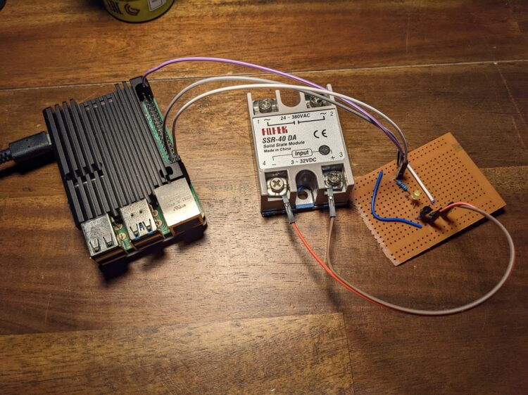
Prototype

With the help of a NPN transistor, a digital pin from a Raspberry Pi can drive a relay

Conclusion

With the help of a transistor or MOSFET, we are now free to drive any relay we want directly from a digital IO pin. We can even switch some really big relays capable of 80 amps or more.

Big-boy-relay

Leave a Reply Cancel reply

Your email address will not be published. Required fields are marked *

Other Posts

  • Hacking a DC to DC converter

    Hacking a DC to DC converter

    Introduction This is a follow-up of a proof of concept I made two months ago. I used an Arduino based DAC (8 bit 8 resistor) and an op-amp to create a signal...
  • How to add dead time to PWM

    How to add dead time to PWM

    There are situations where you absolutely want to avoid signals overlapping one another. This is when you get introduced to the term dead-time. I will give you an example of a circuit...
  • Ten ways to drive a MOSFET, with examples

    Ten ways to drive a MOSFET, with examples

    These are a couple of circuits that can drive a MOSFET. Each of them has their own pros and cons, so whether or not they are useful is highly dependent of what...
  • How to make an op-amp output PWM with duty-cycle control?

    How to make an op-amp output PWM with duty-cycle control?

    We can use a generic op-amp like the LM4562NA. We build an oscillator from the first op-amp in the IC. This produces a triangle-wave. We feed this wave into the second op-amp....
  • How does an op-amp work?

    How does an op-amp work?

    Op-amp is short for operational-amplifier. You can use it as a comparator, buffer a signal, or amplify a signal. These are some op-amps I have; they are the LM358 and the LM4562....

Tools

  • DAC generator
  • Ohms law calculator
  • Inductor calculator
  • Where to get MOSFETs?
©2023 Krakkus.com | Design: Newspaperly WordPress Theme