Voltage to high or to low to analogRead() directly into your microcontroller? With the right resistor-divider, we can read anything we want.
There are three distinct problems, each with its own solution.
Table of Contents
- The positive voltage is above 3.3v or 5v
- The voltage is below ground/negative
- Both voltages are out of range
- Arduino code
- Network generator
- Resistor simulator
The positive voltage is above 3.3v or 5v
If we apply double our maximum voltage over two identical resistors in series, we expect to measure half our voltage at the midpoint. It is this midpoint we are going to measure and feed to analogRead().
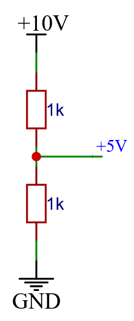
The voltage at the top can be calculated by multiplying the analogRead() voltage by 2. In this example, I will assume a 5V microcontroller.
If we add another identical resistor, we add another 5V to the maximum voltage we can read, we can extend this as many times as we like.
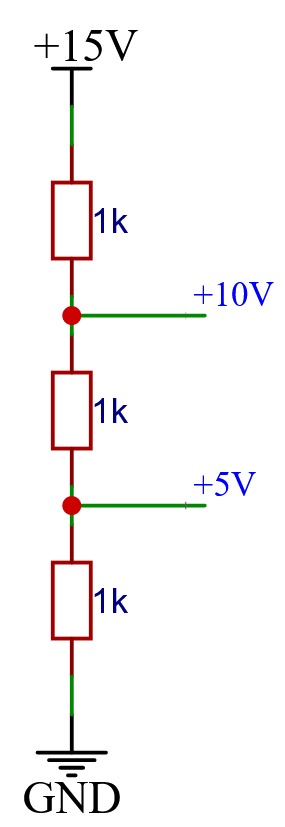
We do only intend to measure after the first resistor, and then multiply the measured voltage by three to get the correct voltage. This means we can group the other resistors together by adding them up.
The voltage is below ground/negative
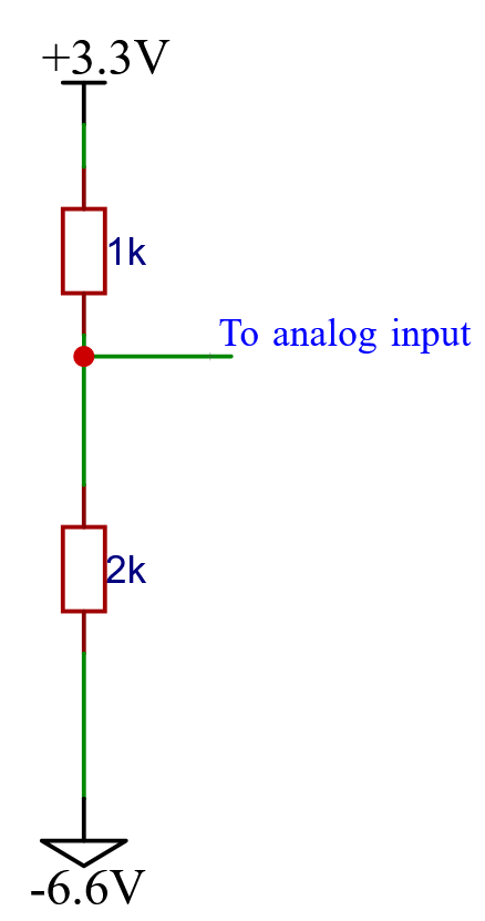
If we want to measure below ground, we have to set this resistor network upside down. This example assumes a 3.3V microcontroller.
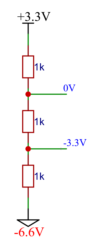
Instead of connecting the bottom end to the ground, we now connect the top to the maximum of our controller. And it is now after the top resistor where we read our voltage.
Once again, we simplify the network to only use two resistors by adding them up.
Calculating the actual voltage is not that complicated. First we multiply the voltage on the analog input by three and then add the lowest voltage we can read on the network, which is -6.6V. On the positive network we did not do this because that value was 0V.
So if we read +3.3V the actual value = (3.3 x 3) – 6.6 = +3.3V.
And if we read 0V the actual value = (0 x 3) – 6.6 = – 6.6V.
Both voltages are out of range
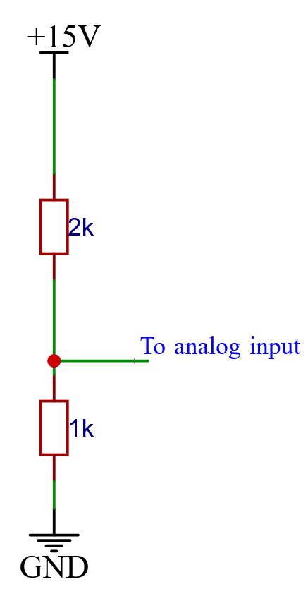
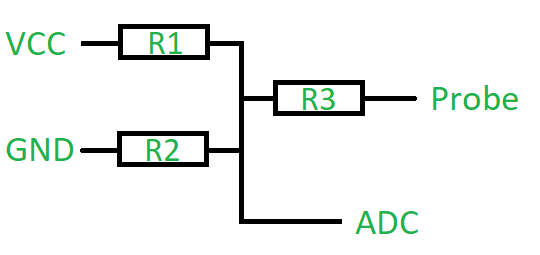
When the input can be below ground as well as above the controller’s maximum, we can’t tie one end of the network to ground or max-voltage. We need to tie it in the middle, using another resistor divider. This example assumes a 5V controller.
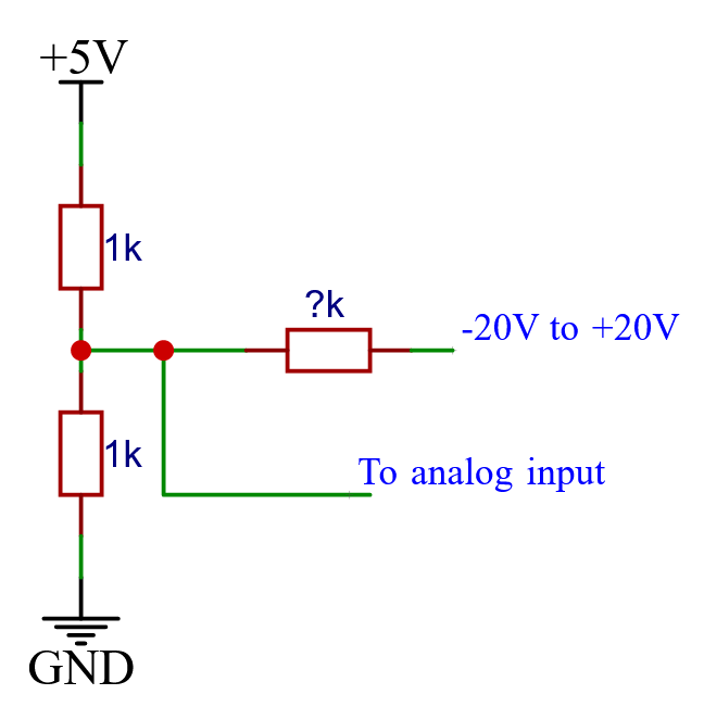
The standing resistors on the left are equal, and without any voltage to measure would produce +2.5V at the middle for the analog pin to read.
The to-measure-voltage applied to the right will then pull that voltage up or down through the third resistor.
Then, how to calculate that third resistor? And how to translate the value read at the analog pin back to the real world value? I could not figure this out in a simple way, so I wrote a tool for it.
You find this tool further down this page.
Arduino code
It doesn’t matter how many resistors your divider has, the voltage at the measuring point always has a linear relation to the actual voltage you are trying to measure.
Therefore, all you need to do is measure two sets of voltages and store them in the map() function. It will then ‘translate’ your new reading into the new actual voltage using these data points.
const int analogPin = A0; // define analog input pin
const float voltageMax = 5.0; // maximum voltage the Arduino can read
void setup() {
  Serial.begin(9600); // initialize serial communication
}
void loop() {
  int analogValue = analogRead(analogPin); // read analog value on pin A0
  float voltageValue = (analogValue / 1023.0) * voltageMax; // convert analog value to voltage
  /*
  To setup the map function we need to sample two voltages and record
  both the actual and midpoint voltage.
  Example: 1K - 1K resistor divider.
  Sample 1: Measure 0V, midPoint is 0V
  Sample 2: Measure 10V, midPoint is 5V
  float actualVoltage = map(midPointVoltage, sampleMP1, sampleMP2, sampleActual1, sampleActual2);
  */
  float actualVoltage = map(voltageValue, 0, 5, 0, 10);

  Serial.print("Analog Value: ");
  Serial.println(analogValue);
  Serial.print("Voltage Value: ");
  Serial.print(voltageValue);
  Serial.println("V");
  Serial.print("Actual Voltage: ");
  Serial.print(actualVoltage);
  Serial.println("V");
  delay(1000); // wait for 1 second
}
Network generator
Designing a three-way-resistor-divider is not as easy as a regular one. So I wrote a script for that.
Just enter the resistors you have, or dump a list of common values in the box. Then add the maximum voltages you expect to measure and hit the compute button. After a few seconds, it will give you the results.
Network generator
Resistor simulator
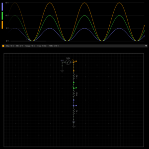
A friend of mine is making an educational tool; a resistor simulator. You can use it to try out different resistor dividers and see what the voltages at the midpoints become.
Hi
Can you provide full Arduino sketch if you please
Hello,
I added some code near the end that should do the job and compiles fine,
but I don’t have an Arduino at work so I will test it later.Code does work.
Hi, I am new to this field so there are things I don’t understand
In the negative voltage, the bottom doesn’t go to the ground but to -6.6V instead.
Where does this -6.6V come from and if the actual voltage changes does it also needs to change? Or does it only need a constant value of twice the maximum voltage that my arduino able to read?
thanks in advance!
Hi Irham,
The -6.6V is the lowest we can possibly measure in this configuration. If we measure any lower, the voltage going to our analog input pin would drop below zero volts/ground.
So in reality, that 6.6V is the thing you want to measure that outputs a negative voltage. And The analog input pin will then see a voltage between 0V and 5V that it can actually measure.
Kind regards,
Krakkus