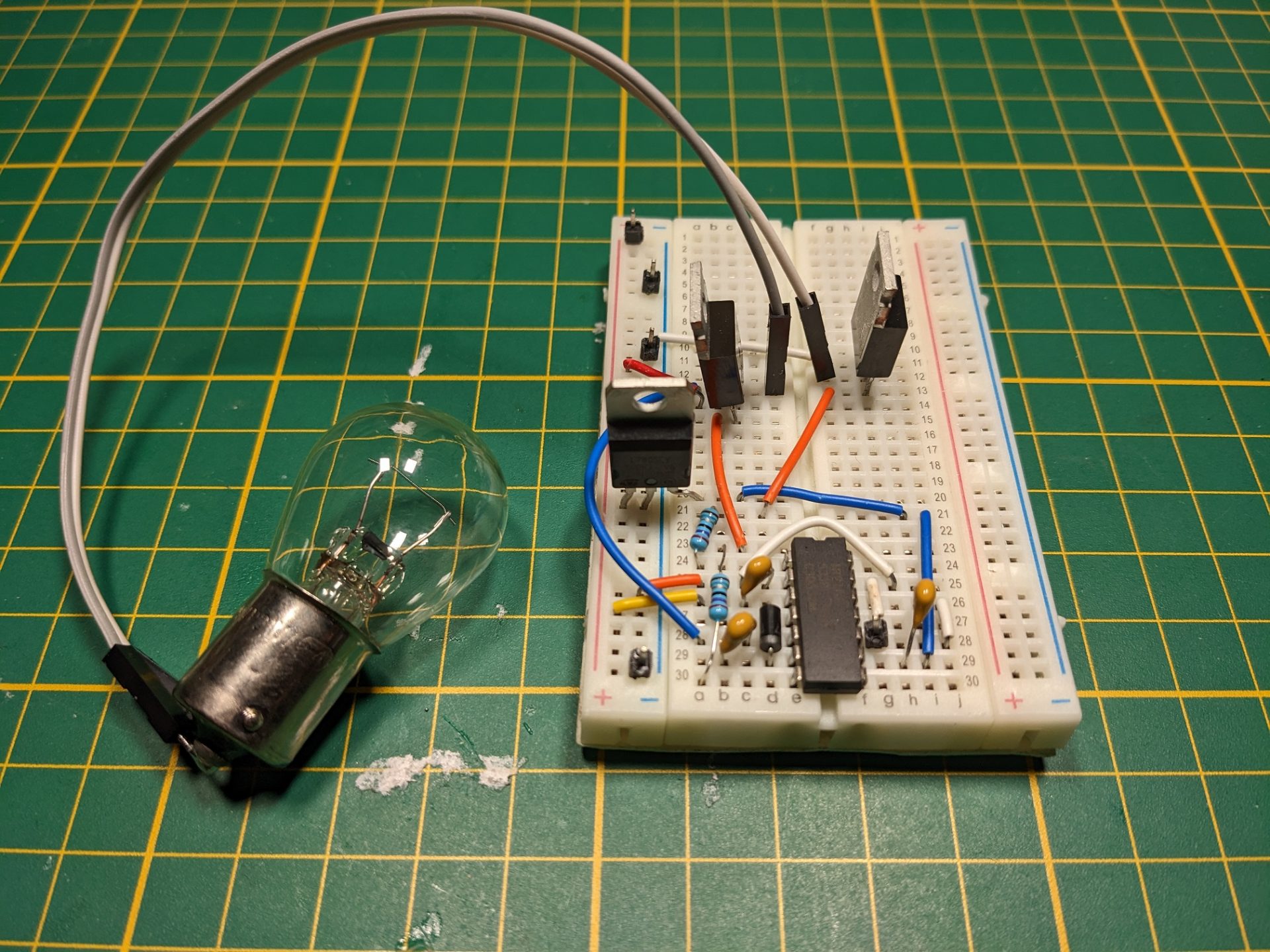
The IR2110 is a very capable high side + low side MOSFET gate driver. It requires a diode and three capacitors to function properly. You can drive the high and low side independently if you like.
IR2110 capabilities
- The IR2110 comes in both DIP and SOIC packages.
- One high side channel. You can switch any side of a load, high, low, in the middle, it’s all good.
- One low side channel. You can switch the ground side of a load.
- Channels are independent. Also, you can use a single channel and ignore the other.
- High side maximum voltage of 500.
- MOSFET gate voltage between 10 and 20. Choose a MOSFET that matches this. Also, you must provide this voltage to the IR2110.
- Can understand logic between 3.3V and 20V. Connect directly to your Arduino, Atmel or PIC. You must provide your logic voltage source to the chip so it knows what to expect.
- Can switch ON and OFF at maximum frequency of 5Mhz. This is more than 50 times faster than an Arduino can do PWM.
Pay attention to pin-out!
The SOIC package of the IR2110 has two extra pins compared to the surface mount packages. This means some pins shifted one place to make room for an unconnected pin. Always check your pin-out for the correct package.
How-to wire it up
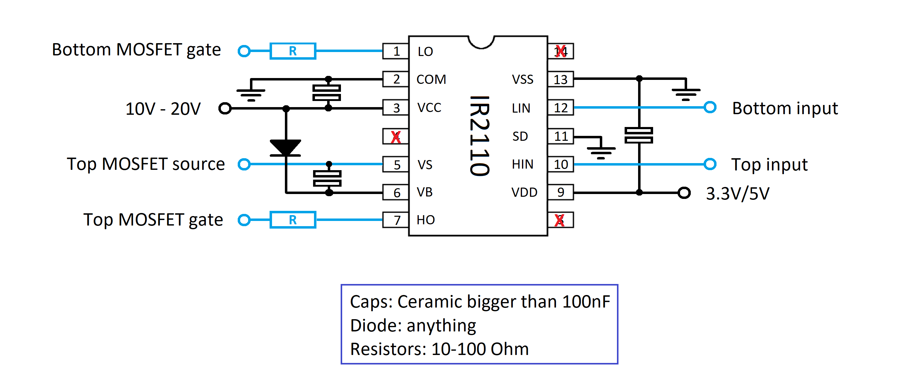
- VCC: Connects to the voltage supply for driving the MOSFET gate. Usually anything between 10V and 20V will be fine. I myself normally give is 12V from and 7812 linear regulator IC. It also needs a capacitor to smooth out the voltage. The other end of the capacitor goes to ground.
- COM: Connects to ground.
- VB: Connects to a bootstrap capacitor which has 10V-20V stored for driving the gate of the high side MOSFET. This is a separate capacitor because it has to float up with the source of the MOSFET. This is why the negative side of the capacitor is connected to the source of the MOSFET. The capacitor is charged through the diode connected to VCC.
- VS: Connect to the source of the high side MOSFET and gives a voltage bias to the bootstrap capacitor.
- LO: Goes to the gate of the low side MOSFET.
- HO: Goes to the gate of the high side MOSFET. The IR2110 connects VB to HO internally to turn the MOSFET on, and connects VB to HO to turn it off again.
- LIN: Is the digital signal to turn the low side MOSFET on or off.
- HIN: Does the same for the high side MOSFET.
- VDD: Connected to the same power supply that powers your controller. This way, the IR2110 knows what to expect for logic high and low. This one also needs a capacitor for smoothing the voltage.
- SD: Connected to ground.
- VSS: Also connected to ground.
Capacitor values
The capacitors are expected to see 20V at the most. I use a 0.1 uF ceramic capacitors in this circuit.
Diodes
Any generic diode will do as long as it can handle 20V.
Suitable MOSFETs
Try finding MOSFET’s close to the voltage you will be switching. If you want to switch 40V, then find a 75V or 100V MOSFET. The lower you keep the voltage, the lower the MOSFET’s on-resistance will tend to be and therefore less heat dissipation. The maximum current often also goes up as the voltage requirement drops.
Video on how to wire the IR2110
Datasheet
Where to buy the IR2110?
You can buy the IR2110 from the regular suppliers like Mouser and Digikey. I personally buy them from eBay and Aliexpress. I know we can expect these to be the same quality as from the original manufacturers, but they work well enough for my projects.