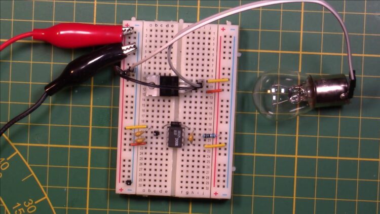
The IR2125 can drive high-side loads up to 500 volts. And only a few external components are needed to use this compact MOSFET gate driver.
Package

The IR2125 is a 8 pin DIP IC
External components
- Capacitors: 100nF or bigger
- Diode
- Gate resistor
The IC is powered with a voltage between 10 and 20. The MOSFET’s gate pin gets to see that same voltage. Any external components has to be able to handle the same voltage.
Pins
| 1 | VCC | Power for the IC itself, 10-20v. Also a good point for the diode to charge the bootstrap capacitor at pin 8 (VB). And it needs a capacitor to keep its input voltage stable |
| 2 | IN | A digital signal, either ground for OFF or bigger than 4.5V for ON. The signal can’t be on continuously. It needs a low signal periodically to charge the bootstrap capacitor. |
| 3 | ERR | Not clear from datasheet. Needs a capacitor to prevent floating. |
| 4 | COM | Ground for the IC. And should be the same as the MOSFET circuits ground. |
| 5 | VS | Connected to the MOSFET source leg and the negative side of the bootstrap capacitor. It is used to either connect the bootstrap capacitor to the gate so the voltage of the gate is 10+ volts relative to the source, or 0v when the gate is discharged to source. |
| 6 | CS | Current censor for MOSFETs that have the extra leg for it. Do not connect. |
| 7 | HO | Output signal that goes to the MOSFET’s gate. Needs a resistor to prevent induction spikes which can kill components. |
| 8 | VB | Bootstrap voltage. Connected to the positive side of the bootstrap capacitor and the receiving end of the diode. The capacitor gets charged when the IN signal is low through the diode. |
Troubleshooting
Make sure the supply voltage has enough current. Switching on the load can dip the supply voltage under 10v for a millisecond and cause the IC to stop working while a multi-meter still shows 10+ volt or higher.
Always connect a load, the IC cannot switch the output high if there is nothing connected to the gate and source pin.
Breadboard connections like the one in the image below are the cause of many problems. Half of the time the exact same circuit did not work and I just rebuild the same circuit to get it to function.
Typical application on a breadboard
