How to use the IR2110 gate driver

The IR2110 is a very capable high side + low side MOSFET gate driver. It requires a diode and three capacitors to function properly. You can drive the high and low side independently if you like.

IR2110 capabilities

  • The IR2110 comes in both DIP and SOIC packages.
  • One high side channel. You can switch any side of a load, high, low, in the middle, it’s all good.
  • One low side channel. You can switch the ground side of a load.
  • Channels are independent. Also, you can use a single channel and ignore the other.
  • High side maximum voltage of 500.
  • MOSFET gate voltage between 10 and 20. Choose a MOSFET that matches this. Also, you must provide this voltage to the IR2110.
  • Can understand logic between 3.3V and 20V. Connect directly to your Arduino, Atmel or PIC. You must provide your logic voltage source to the chip so it knows what to expect.
  • Can switch ON and OFF at maximum frequency of 5Mhz. This is more than 50 times faster than an Arduino can do PWM.
Continue reading “How to use the IR2110 gate driver”

How to use the IR2125 MOSFET gate driver

The IR2125 can drive high-side loads up to 500 volts. And only a few external components are needed to use this compact MOSFET gate driver.

Package

The IR2125 is a 8 pin DIP IC

External components

  • Capacitors: 100nF or bigger
  • Diode
  • Gate resistor

The IC is powered with a voltage between 10 and 20. The MOSFET’s gate pin gets to see that same voltage. Any external components has to be able to handle the same voltage.

Continue reading “How to use the IR2125 MOSFET gate driver”

Creating the 8 bit 8 resistor DAC

I wanted to build an analog output for my Arduino, a DAC.

The default solution is to create a R-2R network like in the picture below.

Classic R-2R resistor network

This resistor network needs 17 resistors to function. I do not have 2k resistors. The only values I have are up to 1 million ohm in these intervals 10, 12, 15, 18, 22, 27, 33, 39, 47, 56, 68, 82.

There is no double value of anything. The only way to make 2k resistors is two in series. So I would need 17+8 = 25 resistors in total.

So then I asked myself; can it be done with only eight resistors? Like in the picture below. The answer turned out to be: Yes, almost, and I had to make a Python script to generate the needed resistor values and combinations.

8 resistor 8 bit DAC
Continue reading “Creating the 8 bit 8 resistor DAC”

Explaining the resistor divider

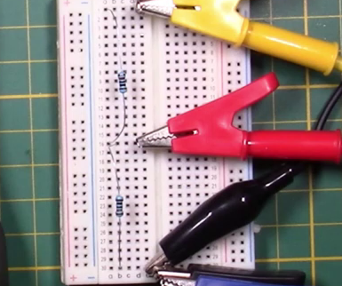
A resistor divider creates a voltage in between the top voltage and ground. In this post I try to explain why that is.

TLDR: It is a result of current going into the midpoint from the top resistor vs current going out through the bottom one. It is because of Ohms law and its linear characteristics that a stable voltage point exists somewhere in the middle.

The experiment

Continue reading “Explaining the resistor divider”

How to power a circuit from high voltage – Repurpose a wall adapter

Table of Contents

Repurpose a wall adapter

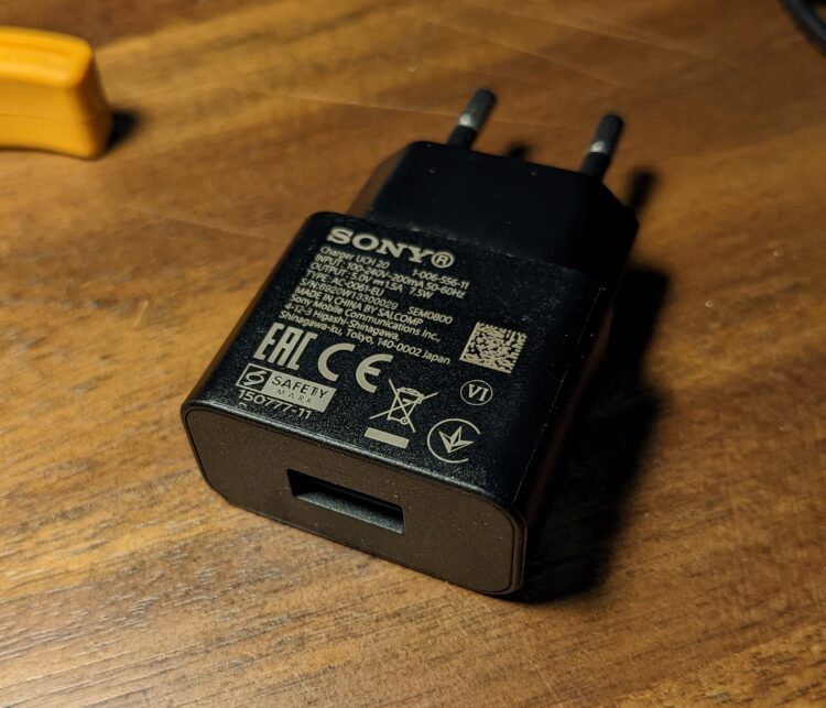
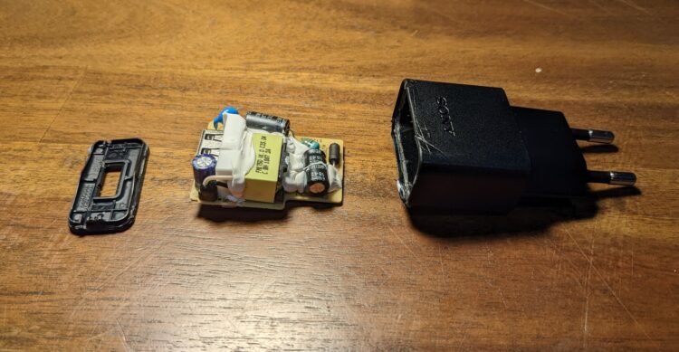
Most of us have wall adapters collecting dust in a box. We can crack these open and reuse the board in it. And then we integrate this into our project. We need to doe the following things

  • Extract the board
  • Add the 5V connections
  • Add the mains connection
  • Connect to the project

Extract the board

If you put the adapter in a vice, just clamp it and apply pressure until it cracks. Then use a screwdriver or spudger to properly open the device. In this case the board had two friction connections to the mains pins so the board came out with little trouble.

Continue reading “How to power a circuit from high voltage – Repurpose a wall adapter”

How to rotate an image in C#

  1. Calculate SIN and COS once
  2. Apply these in a formula to all pixels
  3. Do this in reverse to avoid gaps in the final image

Rotation-matrix

To rotate a pixel around an axis, we need to do some sinus and co-sinus calculation to it because, in short, rotation follows a circular path.

The good part is that the sinus and co-sinus part of the calculation remains the same for every pixel, because they all rotate the same amount.

The next code sets up the values needed later in the main loop. And C#’s math functions want to see Radians, not degrees.

double rotationRadians = userRotate * (Math.PI / 180);

float sin = (float) Math.Cos(rotationRadians);
float cos = (float) Math.Sin(rotationRadians);

In reverse

If we where to go over every pixel in the original image and calculate it’s new position, then there would be gaps in the destination image.

Therefore, we go over every pixel in the destination image, and calculate back where its original position is, that way we always have a pixel color when within the image’s border.

Continue reading “How to rotate an image in C#”

With A Resistor-divider You Can AnalogRead() Anything!

Voltage to high or to low to analogRead() directly into your microcontroller? With the right resistor-divider, we can read anything we want.

There are three distinct problems, each with its own solution.

Table of Contents

The positive voltage is above 3.3v or 5v

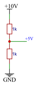
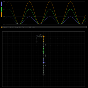
If we apply double our maximum voltage over two identical resistors in series, we expect to measure half our voltage at the midpoint. It is this midpoint we are going to measure and feed to analogRead().

Simple resistor-divider, voltage at midpoint is half the voltage at the top
Simulation of the voltages in a resistor-network, all the voltages are evenly scaled
Continue reading “With A Resistor-divider You Can AnalogRead() Anything!”

How to drive a relay from a digital pin, two solutions

The first is by using an NPN-transistor, and the second a N-channel-MOSFET. Both circuits are pretty much the same otherwise.

NPN transistor

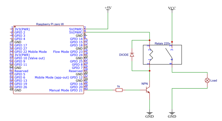
Using a transistor is the cheapest and fail proof way of doing this. Setting a output pin high on your CPU sends a resistor limited current to the base of the transistor.

A multiple of that current is allowed through through the transistor and therefore the relay-coil, powered from the same voltage source as the CPU, but not through it.

Use a NPN transistor to drive a relay from the low side with little current going though the IO pin
Continue reading “How to drive a relay from a digital pin, two solutions”

How to create a power limiter to get zero-on-the-meter to save taxes

If you are one of the many people exporting electricity to the grid, chances are you are familiar with the following…

When you export electricity you also get to pay energy taxes and or other grid fees. So even if your net-consumption is zero, you still own taxes. This might not be the case in your country or your specific utilities provider, but it will be the future for most of us.

With solar you are either importing or exporting power

The graph above is a simplification of typical grid usage for a solar house over the course of 24 hours. At night we consume power from the grid, and at daytime we are exporting. Either way there is power crossing the meter which can potentially cost us money as taxes.

Continue reading “How to create a power limiter to get zero-on-the-meter to save taxes”

How to create a smart switch for an electric boiler to save money

My electric water heater consumes a lot of electricity, and it does so at times when it is most expensive. This is because I have dynamic prices which change every hour and I shower at an expensive time. And even if a had a high&low tariff, the problem would still exist.

Most people shower at an expensive moment!

There is more than one way to solve this problem, and I prefer one that is technological in nature.

Continue reading “How to create a smart switch for an electric boiler to save money”